A few people have asked how I create the circuit diagrams which I put on my blog - for example:
I use the draw tools built into LibreOffice - a free Office application which runs on Windows, Mac and Linux. In the past, I used the PowerPoint draw tools in Microsoft Office which was licensed through my place of work. Now I am retired, I use the equally powerful suite of applications in LibreOffice (formely OpenOffice).
To keep things simple and straightforward, we'll draw this simple circuit using all the techniques which are needed to draw more complex diagrams such as that shown above.
Please note: All screenshots shown below can be enlarged by clicking on them.
With LibreOffice installed, I open it up and select the Draw Application.
This then takes me to the drawing screen:
The first thing I tend to do is change the orientation of the canvas to landscape using the page properties sidebar:
If the sidebar isn't showing, this can also be achieved by selecting Page properties from the Page menu .....
.... and then clicking the Landscape radio button.
I then gather the images I require for the diagram by searching the internet using image search.
Once I have accumulated most of the images needed (there's always one or two I miss initially), .....
..... I identify any which might need to be cropped if their background is larger than it needs to be, such as this one.
I then use Paint to crop the image to ensure there is very little white space around it. Start up Paint (it's usually a freebie which comes with your Windows computer (Apple Mac users either have MacPaint or Preview, depending on the age of their machine)).
Once Paint is up and running, the image we want to crop can be loaded by using Open from the Edit menu
The Selection tool (top left corner of the window) is clicked and a dotty box is drawn around the image, getting it as tight as possible to the image. It may take a few goes at this; just click off the image and start again.
The image can then be cropped either using the Crop tool (beside the Selection Tool) or right-clicking on the image and choosing Crop from the pop-up menu.
We can now start positioning some of the images on the drawing canvas of LibreOffice Draw.
To insert a saved image, Image is selected from the Insert menu.
We can then navigate to where the required image was saved, and click Open.
I usually start with the battery pack - not sure why, but it seems to make sense.
Once inserted, as you can see, the battery is far too large and so needs to be reduced in size. This is achieved by clicking on one of the 'handles' on one of the corners of the image and dragging it diagonally inwards.
Once it is roughly the right size, the next job is to duplicate it and swivel it round because we need two cells in our battery pack.
This is done by clicking on the image and selecting Copy from the Edit menu, or right-clicking the image and selecting Copy from the pop-up menu. ......
Clicking Paste in the Edit menu will create a copy of the image (in this case the AA cell). The copied image appears on top of the old image and so will need to be dragged to a new position alongside the original.
Once dropped in its new position, it needs to be rotated so it is upside down. The image is clicked on once, and then clicked again. The handles change from white squares to green circles with an orange circle over the middle, showing it is in rotate mode.
If we now click and hold any one of the green corner handles, the image can be rotated by dragging the handle around, ......
.... until it has reached its required orientation. We then unclick to fix it in position. If it requires further rotation or tweaking, the process can be repeated until you are happy with its position.
We can now use the same processes to position the other items needed for our diagram.
There's no right or wrong way to position the components. Traditionally, circuits have a negative rail at the base of the screen, but I prefer to place them in the relative positions they will be inside the loco.
Now we have the components in place (they can easily be moved later if needs-be), we can start linking them together.
As the connection for the push-button is directly above the positive terminal of one of the cells, we'll link them together with a simple straight line.
To do this, we click on the Lines and Arrows Tool in the toolbox on the left of the screen, and then select Insert Line.
The cursor now changes to a cross-hair with a line beside it, showing we are using the Line tool. Click on the connector below the push-button and, with the mouse-button (or tracker button) held down, drag the line to the terminal of the AA cell below it.
The handles on the ends of the line allow you to re-position them, by clicking on them and dragging. If you need to try again, click on the line to highlight it and press the delete key on the keyboard. You can then repeat the process.
We now need to change the colour and thickness of the line. Highlight the line you've just drawn by clicking on it, then select the required line colour (in our case, red) from the Color palette in the Toolbar on the right of the screen.
NOTE: If your toolbar isn't visible, right-click on the line you have just drawn and select Line from the pop-up menu.
To change its thickness, click on Width in the Toolbar and select the required thickness (I tend to go for 3pt or sometime 4.5pt)
Next, we'll link the other connector on the push-button to the resistor. To do this we click on the Curves and Polygons button in the toolbox on the left of the screen, and then select the Polygon (45°) tool.
With the Polygon(45°) tool selected (the cursor should change to show this), we click on the connector below the push button and then with the left mouse-button held down, drag a line stright down until we are opposite the resistor. We then release the mouse button, click again and drag the next line to the resistor. We then double-click the left mouse-button to finish off the shape.
At this stage, we can tweak the position of the lines by clicking on one of the middle handles on the shape and dragging them to widen or narrow the L shape we have just drawn.
To change the width and colour of the new line, click on it to highlight it and then choose the required Color and Width from the toolbox on the right of the screen (or right-clicking and selecting Line from the pop-up menu) - as we did with the line above.
To create the link from the resistor to the leg of the LED, we could repeat the above process, but instead, we'll copy and paste the L-shaped link we just drew.
To do this, click on the L-shaped link and then click Copy in the Edit menu (or right-click on the L-shape and select Copy from the pop-up menu)
We now click Paste in the Edit (or pop-up) menu. The copied L-shape link will be pasted on top of the original L-shaped link, so we can drag it over to the other side of the resistor. To drag the shape, click and hold down the left mouse button on any of the lines (rather than the handles).
Now we need to flip the new L-shaped link, resize it to fit the gap between the resistor and the LED leg and drag it to ensure it lies up correctly.
This is easily achieved by dragging the square-shaped handles on the shape.
To flip it horizontally, we drag one of the middle side handles completely across the shape and out the other side.
We can now move it by dragging on the lines and resize it by dragging the handles until it lines up with the resistor and the LED leg.
Using the above processes, we can now add and colour all the other links.
The next stage is to add the coloured dots to show where links are joined to components (or with more complex diagrams, to each other)
A dot is made using the ellipse tool from the left-hand toolbox.
With this tool selected (check the shape of the cursor), we draw a small circle anywhere on the canvas.
NOTE: It is easier to do this if you zoom in to the canvas using the + magnify button in the bottom right corner of the screen.
NOTE: To get a circle rather than an ellipse, hold the Shift key down while you drag the shape to size.
The dot can now be coloured, using the Color buttons in the Line and Area toolbars on the right of the screen (or the right-click pop-up menu)
The dot can be dragged to where it's needed. It's all too easy to accidentally drag one of the handles and resize the dot rather than moving the shape. If this happens, you can undo the accidental resizing by clicking Undo in the Edit menu (or holding down the CTRL key and tapping the Z key on the keyboard).
The dot can now be copied, pasted and dragged to the other link ends.
The black and blue dots can either be drawn from scratch or a red dot dragged into position and its colour changed as above. In this way, all the dots can now be added to the diagram.
NOTE: If you want a line, a dot or an image to appear on top of or behind another line, dot or image then right-click on one of the shapes to highlight it, then select Arrange from the pop-up menu.
From the pop-up sub-menu we can then select Bring to Front or Send to Back, dependent on what we want the clicked shape to do.
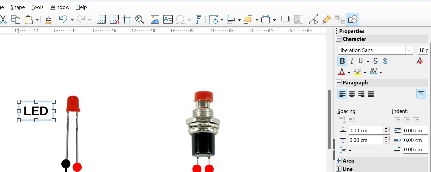
Finally, we need to add the labels to the diagram.
We select Text Box from the Insert menu
The cursor will change and enable us to drag a box on the canvas roughly where we want the text to appear.
We can now type into the box the label required.
To change the text size, style or font, we can either drag over the text to highlight it (especially if you want only part of the text in the box to be changed) or click off the text box and then click back on it once to highlight the box and then selecting the required properties from the Character or Paragraph tool box on the right of the screen (or the right-click pop-up menu)
Once all the labels have been added, we are ready to save and export the diagram.
To save the drawing, select Save As... from the Edit menu and save it where you will be able to find it again. This will save a LibreOffice draw file (.odg) so you will be able to re-open it and make changes in the future.
To export the diagram as an image file (eg .JPG, .GIF, .PNG, etc) so it can be inserted into a document, sent by email or inserted into a web page, firstly select all the items on the screen. This can be done either by dragging the Select tool over all the items on the canvas .....
..... or simply by holding down the CTRL key and tapping the A key on the keyboard.
With all the shapes highlighted, we now select Export from the Edit menu
We can now type in a file name for the diagram and choose the type of image file we want it to be saved as (in this case, a .JPEG file).
Before we click the Save button, we need to tick the Selection box.
The reason for this is to ensure the exported image includes only the items we have drawn. If not, the whole canvas is exported which might contain a lot of white space around the main drawing.
There is no need to change the default properties of the exported diagram unless you want to enhance or degrade its quality or amend the size of the exported image - so just click OK.
The diagram is now complete and ready to use.
I hope you have found this little tutorial useful. If you have any questions, observations or feedback, then please let me know via the comments below.
 Introduction


