I have four Deltang transmitters, a Tx22 which I bought readymade (before I realised how easy they were to construct from kits), a Tx21 (built from a kit), a Tx27 (built from a kit) and a Tx20 whose construction is described here. I have also included some photos and observations of the construction of a Tx22 kindly supplied to me by a fellow modeller, Dave Bowden (see below).

.....and instruction sheets.

Also included was a diagram showing the position and size of the holes needed in the case .....

.... and a circuit diagram which I found to be essential for ensuring the leads and resistors were connected correctly. As you can see, it is very easy to follow. As the receiver is already constructed, all that was required was to connect it to the buttons, switch and potentiometer with wires (not provided) and/or the resistors which came in the kit.

These sheets are also available as downloads on the Deltang website. I decided to download and print out the photos showing the construction process on the sheet as a further guide to construction.

Having made my preparations, I was ready to start construction.

The position of the hole for the direction switch was marked 10mm from the top edge and central across the width.
The position of the holes for the buttons on the end of the case were marked 8mm from the base, 6mm from the front and 15mm in from each edge.

A 6mm holes was then drilled for the reverse switch and a 7mm hole for the speed control potentiometer. The reverse switch hole was opened out a little with a round needle file (the diagram suggests 6.35mm).

Three 7mm holes an a 9mm hole were drilled in the end of the case. The 9mm hole was opened out a little (to 9.3mm) and a small notch filed at the front to take the locating peg on the on/off switch.

The reverse switch and potentiometer were then fitted into the holes and their nuts tightened.

I decided to position the direction switch horizontally rather than vertically as shown in the photos on the Deltang website.

The push-buttons were then pushed into their relevant holes in the end of the case.

When I fitted the knob to the potentiometer spindle, ......

..... I realised the pot was upside down and so it was swivelled through 180 degrees. This meant the wiring in the photos on the instruction sheet would need to be altered slightly, but that was no major problem.

I was now ready to start the wiring.

One of the 18k (brown-grey-black-red (brown)) resistors was soldered across the other two leads on the 100k resistors.

The leads were then snipped to be the same lengths......

The resistors were then soldered to the terminals of the direction switch, At the same time the 470R (yellow-violet-black-black (brown)) resistor was soldered from the left terminal of the switch to the right terminal of the potentiometer and covered in heatshrink [in fact a 220R (red-red-black-black (brown)) was supplied and used].

Next, attention was given to connecting up the negative (0v) leads to the push buttons. Firstly, the shorter lead of the LED in the on/off switch was soldered to one of the on/off switch terminals and then to one of the terminals of the adjacent push-button.

Next, a wire was soldered from the terminal of the potentiometer to which the 470R had been connected, to one of the terminals of the other push-button and then on to one of the terminals of the last remaining push-button. This formed the basis of the 0v (negative) wiring loom to which all the push buttons are connected.

Finally, a wire was soldered across, linking the 0v terminals of all the push-buttons together.

One lead of the second 18k (brown-grey-black-red (brown)) resistor was soldered to one of the leads of 10k (brown-black-orange (brown)) resistor. The other lead of the 10k resistor was then soldered to the left terminal of the potentiometer and the 18k resistor was shrouded in heatshrink sleeving and soldered to the right hand terminal of the direction switch.
A piece of heatshrink sleeving was slipped on to the black lead from the battery connector and this was then soldered to the right hand terminal of the on/off switch.

A piece of heatshrink sleeving was slipped on to the red lead from the battery connector and the lead then soldered to one of the middle row of pins on the Tx2 receiver. In the photos on the Deltang website, the leads are soldered to the pins nearer the circuit board. I prefer to solder them to the ends of the pins so I can slip heatshrink sleeving over the joints. Others prefer to use JST sockets (eg see Dave Bowden's Tx22 photos and description below).

A wire was then soldered to the unused terminal of the bind button beside the on/off switch .......

..... shrouded in heatshrink ......

.... and then soldered to the uppermost pin 5 on the transmitter board.

A wire was then soldered to the unconnected terminal of the uppermost push-button on the left hand side of the case .....

..... and shrouded in heatshrink.

The other end of the wire was soldered to pin 4 on the transmitter and shrouded in heatshrink.

A wire was then soldered to the unused terminal of the lowermost push-button on the left and covered by heatshrink.

The other end of the wire was then soldered to pin 2 of the transmitter and covered in heatshrink.

A wire was soldered to the central terminal of the pot ....

.... and its other end soldered to pin 1 of the transmitter. Both ends were shrouded in heatshrink.

A wire was soldered to the right hand terminal of the pot .........

..... and its other end soldered to one of the lowermost pins on the transmitter, to connect it to the 0v wiring loom.

A wire was soldered to the central terminal on the direction switch .......
...... and its other end soldered to pin 3 on the transmitter.

Finally, the two pads (pin 8 and the 3.1v output) on the transmitter board were tinned with solder ......

...... and wires soldered on to these pads.

The other end of the 3.1v lead was then soldered to the connection between the 10k and 18k resistors, and shrouded in heatshrink.

The other end of the wire from pin 8 was soldered to the positive lead of the LED protruding from the base of the on/off switch. This too was shrouded in heatshrink.

A final check was made to ensure that all the wiring shown on the circuit diagram was present, that none of the wiring was loose and that no bare wires were touching, and then a battery was attached to the battery and the on/off switch depressed.

Fortunately, everything seemed to be functioning as expected and so the transmitter board was inserted into the clear heatshrink sleeve provided with the kit and the clear acetate sheet bent around the battery. The battery and transmitter board were carefully inserted into the case .......

..... and the back of the case screwed into place.

The transmitter was then bound to the Rx65b receiver in one of my locos (Loco No. 6 - Manning Wardle - Harthill) and both were taken out into the garden for a test-run (or three!).

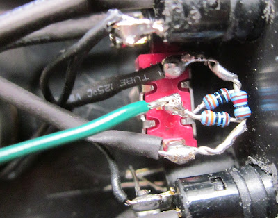
The selector switch that comes with the kit is a PCB type, not one with eyelets on the ends, so Dave bent the pins over 90 degrees to make soldering easier.

He then added the resistors around the selector switch using 22swg 0.7mm cored solder to ensure that he didn't end up with large amounts of solder on the small resistors. Although it looks quite daunting, he started on pin 12 and worked round to pin 1 soldering one pin with two resistor legs at a time. This enabled the resistor leg to be bent for the next pin. He also added R35 to pin one and R36 to pin 12 leaving a short leg to attach wires; one to being connected to the 3.1V rail and the other to the 0v rail (see below)

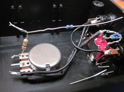
Dave mounted the potentiometer and switches to the lid of the case rather than the case itself - which made soldering and access a lot easier. He also glued (with two-part rapid epoxy) a couple of small pieces of PCB to the case to act as bus bars for the 3.1v and 0v connections. In this photo you can see that he's fitted all the remaining resistors and the wiring to the two power bus bars. He has also added the two wires that have to be soldered to the transmitter board (ie to the 3.1v and Pin 8 pads). You'll notice that Dave's wiring is a lot tidier than mine. Clearly, his experience of wiring telephone exchanges has stood him in good stead.

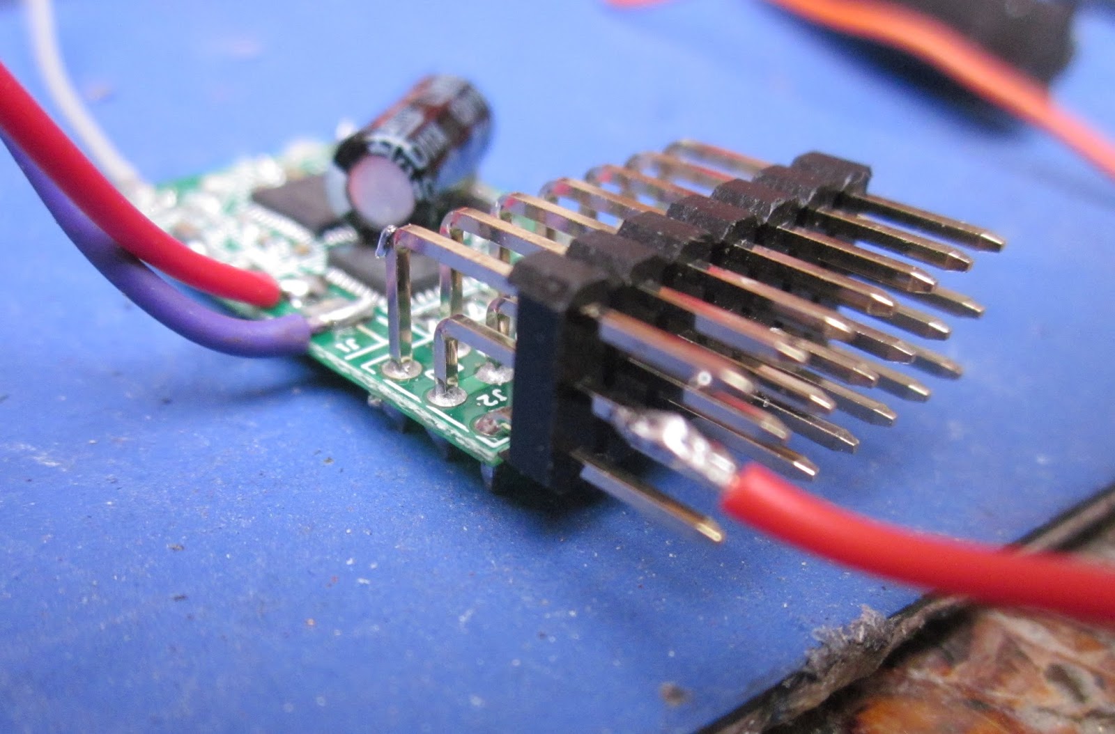
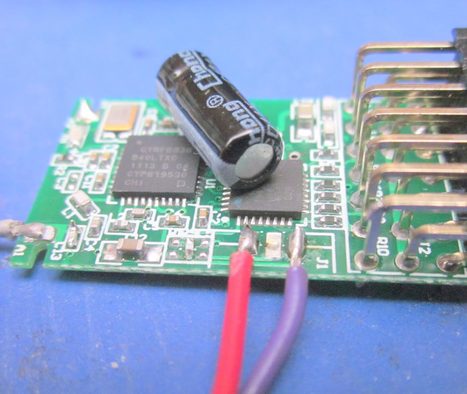
He used JST connectors for the five wires connected to the pins of the transmitter, using the thinnest wire he had available to connect these to the various switches. The Tx2 transmitter was turned upside down and positioned just in front of the battery. The thin plastic sleeve provided in the kit was fitted over the circuitry up to the pins.

Dave replaced the knob for the selector switch supplied with the kit with one from Maplin, as the supplied knob was too small to mask the nut mounting it to the case. This knob was from the same range as the speed knob but the next size down (24mm dia and 20mm height) (Maplin code FK40).

 I hope you find these descriptions helpful and that we have shown how the construction of the Deltang transmitter kits is not too daunting. The construction of my Tx20 took approximately three hours in total. I took a systematic approach, following the photos on the Deltang website and double checking the connections on the circuit diagram.
All I can say is that if I can build three successful transmitter kits (my Tx20, a Tx27 (see How I operate some of my points by remote control) and a Tx21), then anyone should be able to do it - at considerable saving on the price of the completed transmitter.

Preparation for the build
The kit arrived with all the necessary components, the case ......
.....and instruction sheets.

Also included was a diagram showing the position and size of the holes needed in the case .....

.... and a circuit diagram which I found to be essential for ensuring the leads and resistors were connected correctly. As you can see, it is very easy to follow. As the receiver is already constructed, all that was required was to connect it to the buttons, switch and potentiometer with wires (not provided) and/or the resistors which came in the kit.

These sheets are also available as downloads on the Deltang website. I decided to download and print out the photos showing the construction process on the sheet as a further guide to construction.

Having made my preparations, I was ready to start construction.
Marking out and drilling the case
I could have cut-out and taped the hole-cutting templates to the outside of the case, but decided to transfer the measurements from the drawings to the case. The position of the hole for the control knob was marked by drawing two diagonals to ensure it was in the centre.
The position of the hole for the direction switch was marked 10mm from the top edge and central across the width.
The position of the holes for the buttons on the end of the case were marked 8mm from the base, 6mm from the front and 15mm in from each edge.

A 6mm holes was then drilled for the reverse switch and a 7mm hole for the speed control potentiometer. The reverse switch hole was opened out a little with a round needle file (the diagram suggests 6.35mm).

Three 7mm holes an a 9mm hole were drilled in the end of the case. The 9mm hole was opened out a little (to 9.3mm) and a small notch filed at the front to take the locating peg on the on/off switch.


I decided to position the direction switch horizontally rather than vertically as shown in the photos on the Deltang website.

The push-buttons were then pushed into their relevant holes in the end of the case.

When I fitted the knob to the potentiometer spindle, ......

..... I realised the pot was upside down and so it was swivelled through 180 degrees. This meant the wiring in the photos on the instruction sheet would need to be altered slightly, but that was no major problem.

I was now ready to start the wiring.
Wiring up the transmitter
The legs of the two 100k (brown-black-black-orange (brown)) resistors were twisted and soldered together.
One of the 18k (brown-grey-black-red (brown)) resistors was soldered across the other two leads on the 100k resistors.

The leads were then snipped to be the same lengths......

The resistors were then soldered to the terminals of the direction switch, At the same time the 470R (yellow-violet-black-black (brown)) resistor was soldered from the left terminal of the switch to the right terminal of the potentiometer and covered in heatshrink [in fact a 220R (red-red-black-black (brown)) was supplied and used].

Next, attention was given to connecting up the negative (0v) leads to the push buttons. Firstly, the shorter lead of the LED in the on/off switch was soldered to one of the on/off switch terminals and then to one of the terminals of the adjacent push-button.

Next, a wire was soldered from the terminal of the potentiometer to which the 470R had been connected, to one of the terminals of the other push-button and then on to one of the terminals of the last remaining push-button. This formed the basis of the 0v (negative) wiring loom to which all the push buttons are connected.

Finally, a wire was soldered across, linking the 0v terminals of all the push-buttons together.

One lead of the second 18k (brown-grey-black-red (brown)) resistor was soldered to one of the leads of 10k (brown-black-orange (brown)) resistor. The other lead of the 10k resistor was then soldered to the left terminal of the potentiometer and the 18k resistor was shrouded in heatshrink sleeving and soldered to the right hand terminal of the direction switch.

A piece of heatshrink sleeving was slipped on to the black lead from the battery connector and this was then soldered to the right hand terminal of the on/off switch.

A piece of heatshrink sleeving was slipped on to the red lead from the battery connector and the lead then soldered to one of the middle row of pins on the Tx2 receiver. In the photos on the Deltang website, the leads are soldered to the pins nearer the circuit board. I prefer to solder them to the ends of the pins so I can slip heatshrink sleeving over the joints. Others prefer to use JST sockets (eg see Dave Bowden's Tx22 photos and description below).
A wire was then soldered to the unused terminal of the bind button beside the on/off switch .......

..... shrouded in heatshrink ......

.... and then soldered to the uppermost pin 5 on the transmitter board.

A wire was then soldered to the unconnected terminal of the uppermost push-button on the left hand side of the case .....

..... and shrouded in heatshrink.

The other end of the wire was soldered to pin 4 on the transmitter and shrouded in heatshrink.

A wire was then soldered to the unused terminal of the lowermost push-button on the left and covered by heatshrink.

The other end of the wire was then soldered to pin 2 of the transmitter and covered in heatshrink.

A wire was soldered to the central terminal of the pot ....

.... and its other end soldered to pin 1 of the transmitter. Both ends were shrouded in heatshrink.

A wire was soldered to the right hand terminal of the pot .........

..... and its other end soldered to one of the lowermost pins on the transmitter, to connect it to the 0v wiring loom.

A wire was soldered to the central terminal on the direction switch .......

...... and its other end soldered to pin 3 on the transmitter.

Finally, the two pads (pin 8 and the 3.1v output) on the transmitter board were tinned with solder ......

...... and wires soldered on to these pads.
The other end of the 3.1v lead was then soldered to the connection between the 10k and 18k resistors, and shrouded in heatshrink.

The other end of the wire from pin 8 was soldered to the positive lead of the LED protruding from the base of the on/off switch. This too was shrouded in heatshrink.

A final check was made to ensure that all the wiring shown on the circuit diagram was present, that none of the wiring was loose and that no bare wires were touching, and then a battery was attached to the battery and the on/off switch depressed.

Fortunately, everything seemed to be functioning as expected and so the transmitter board was inserted into the clear heatshrink sleeve provided with the kit and the clear acetate sheet bent around the battery. The battery and transmitter board were carefully inserted into the case .......

..... and the back of the case screwed into place.

The transmitter was then bound to the Rx65b receiver in one of my locos (Loco No. 6 - Manning Wardle - Harthill) and both were taken out into the garden for a test-run (or three!).

Dave Bowden's Tx 22 construction
I am very grateful to Dave Bowden for the photos and description shown below of the build of his Tx22. Dave is a former electronics engineer and, as can be seen from his photos, has a lot more experience of keeping his wiring neat and tidy.The selector switch that comes with the kit is a PCB type, not one with eyelets on the ends, so Dave bent the pins over 90 degrees to make soldering easier.

He then added the resistors around the selector switch using 22swg 0.7mm cored solder to ensure that he didn't end up with large amounts of solder on the small resistors. Although it looks quite daunting, he started on pin 12 and worked round to pin 1 soldering one pin with two resistor legs at a time. This enabled the resistor leg to be bent for the next pin. He also added R35 to pin one and R36 to pin 12 leaving a short leg to attach wires; one to being connected to the 3.1V rail and the other to the 0v rail (see below)

Dave mounted the potentiometer and switches to the lid of the case rather than the case itself - which made soldering and access a lot easier. He also glued (with two-part rapid epoxy) a couple of small pieces of PCB to the case to act as bus bars for the 3.1v and 0v connections. In this photo you can see that he's fitted all the remaining resistors and the wiring to the two power bus bars. He has also added the two wires that have to be soldered to the transmitter board (ie to the 3.1v and Pin 8 pads). You'll notice that Dave's wiring is a lot tidier than mine. Clearly, his experience of wiring telephone exchanges has stood him in good stead.

He used JST connectors for the five wires connected to the pins of the transmitter, using the thinnest wire he had available to connect these to the various switches. The Tx2 transmitter was turned upside down and positioned just in front of the battery. The thin plastic sleeve provided in the kit was fitted over the circuitry up to the pins.

Dave replaced the knob for the selector switch supplied with the kit with one from Maplin, as the supplied knob was too small to mask the nut mounting it to the case. This knob was from the same range as the speed knob but the next size down (24mm dia and 20mm height) (Maplin code FK40).


All I can say is that if I can build three successful transmitter kits (my Tx20, a Tx27 (see How I operate some of my points by remote control) and a Tx21), then anyone should be able to do it - at considerable saving on the price of the completed transmitter.

No comments:
Post a Comment