 When I first built my railway I had two gaps which needed to be bridged - one spanning access to the sheds and one crossing the path to the small patio area behind Peckforton Station. Although there would be no necessity for major engineering works on the route which my hypothetical Peckforton Railway follows, I felt two reasonably realistic bridges should be built to cosmetically enhance the planks which initially bridged these gaps.
The longer plank over the access to the sheds was prettified by constructing a representation of the original swing bridge across the River Blyth at Southwold (see How I constructed the swing bridge).

Rather than a metal bridges, I felt a viaduct built from the local sandstone would be more appropriate for the shorter span across the patio entrance.

However, as it had to be removable, I wanted something reasonably lightweight, rather than using the cast concrete approach I'd used previously on the overbridges (see How I cast two overbridges in concrete).

I researched suitable prototypes on the internet before opting for the Arthington Viaduct as the inspiration for my structure.
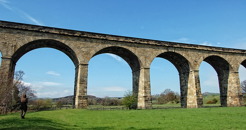 |
| Arthington Viaduct: Source Tom Blackwell - http://www.godsowncounty.co.uk/yorkshire/arthington-viaduct-photos/ |
The structure
The plank supporting the track had been in place for several years, comprising a piece of one inch thick by six inches wide pressure treated fencing rail. This was retained. The sides were cut from a sheet of 4mm thick exterior grade plywood with a power jigsaw.
A card template was shaped to ensure the arches were of a consistent shape and size. As I wanted to ensure that each end of the viaduct finished on the middle of an arch, I calculated that the arches needed to be 135 millimetres wide with pillars 40mm wide.

To ensure the ends of each side would butt cleanly to the stonework on either side of the pathway, cardboard templates were cut out. The irregular profiles were drawn by rubbing the card over the irregularities of the rockface andc then trimming and adjusting until the card template fitted.


The templates were then used to transfer the outlines to the plywood sides of the viaduct.


'Stone' cladding for the sides
Having already experimented with using shaped balsa sheet for random stone walling (see How I constructed the buildings for the copper mine - pending), I decided a similar approach could be used for representing the blockwork on the viaduct. To keep things simple, I decided that the blocks on my viaduct would all be 10mm in height.To give the impression of extra depth, the lower four courses of blocks at the base of each pier were cut from 3/16 inch (5mm) thick balsa; the other blocks being cut from 3/32 inch (2.5mm) thick balsa.
10mm wide strips were initially cut from the balsa sheets. The edges of the strips were then carefully bevelled with a craft knife. I found that it was easier to get more consistency in the bevelling if the balsa sheets were places on a cutting mat and the knife run along at about a 45 degree angle. I felt that it did not matter too much if there were some inconsistencies in the bevelling as each block would have been shaped by hand by a stone mason on the real thing.

The width of each block on the piers was calculated dependent on the width of the pier for the particular course of blocks being laid as the piers tapered from bottom to top. Alternate courses contained either two or three blocks and so the calculation took account of the width of the pier (w), plus an overlap either side equal to the thickness of the block (eg 4.75mm x 2 = 9.5mm), minus either one or two millimetres for the mortar courses between the blocks, depending on whether there were two or three blocks in the course. The overlap was to take account of the blocks which would be laid on the insides of the arches.

The ends of the blocks were then bevelled with a craft knife and the blocks glued on with exterior PVA adhesive.

Once the piers had been clad, .......

the voussoirs around the curve of the arches were cut and applied. These were 15mm tall, 10mm at the top, tapering down to around 7.5mm at the base.

They were shaped and bevelled in the same way as above.

The keystone of each arch was 20mm tall, and made slightly broader at the top. The keystone was attached first, to ensure it was central, .....

...... and the remaining voussoirs glued on alternate sides until they reached the final springer at the base.

A horizontal ledge made from 3/8 inch thick balsa was then cut and fixed across the top of each pier. A second ledge was attached 35mm from the top of the parapet.

Below this, a row of 3/16 inch thick, 10mm x 15mm blocks was laid.

The blocks filling the triangular sections at the top of each pier were shaped individually, assuming that a whole block was 10mm x 15mm.

Initially, I worked from the lowermost ledge to the uppermost, but after filling the first section, realised it was a lot easier to work from thew top downwards.

When it came to applying the blocks to the sides of the parapet above the ledge, I needed dozens of 10mm x 15mm blocks, and so I devised a method of mass production. After the 10mm wide strips had been marked out, a strip of four rows was cut and marked out at 15mm intervals.


The 10mm wide strips were then cut,

...... and their edges bevelled with a craft knife.

I found that some strips could be cleanly snapped at the notches, while others, if the balsa was firmer, needec to be sliced with a razor saw.

This approach was more efficient than individually bevelling each block. Once a collection of blocks had thus been made, .......

......... applying them to the parapet sides was a relatively quick and easy process.

For the capping stones along the top of each parapet, 30mm x 10mm blocks of 3/16 inch thick balsa were cut, bevelled and then glued on.

Underneath the arches
Once the sides had been clad, I widened the plank carrying the track with a couple of strips of 1.5 inch wide by 1 inch thick treated fence rail. The vertical inside faces of the piers were made from 4mm thick plywood, glued to 12mm square section stripwood.

A similar cardboard template approach was used to profile the two end piers to ensure they butted neatly to the rockfaces.

For a while, I considered all manner of ways of achieving the curved underside of the arches, such as very thin plywood, but in the end went for 6mm x 15mm stripwood glued to 12mm square battens.

It turned out that the two sides were not perfectly aligned with each other. In hindsight I should have double and triple checked this when shaping the ends of each side against the rockfaces. However, this slight skewing is not immediately obvious when looking at the viaduct, it just meant that the geometry of the cross pieces was slightly more complicated. By rights, these should have been trapezoidal in shape, but as they were going to be concealed by the cladding, I was happy to live with the small gaps at the ends of each cross piece.

Once the insides of the piers and arches had been filled, I was ready to clad them with balsa blocks.

Cladding the arches
Scrutinising the photos of my chosen prototype, it appeared that the insides of the piers were constructed from alternate rows of shorter and longer stone blocks. To keep things simple, I mass produced blocks of width 10mm and length 15mm for the shorter blocks and 30mm for the longer blocks.
Before infilling the courses, quoins were cut and glued on, taking the side blocks around the corners to the inside faces of the piers.

The ledges at the lower end of each arch were extended across the insides of the piers. To ensure the vertical mortar courses were staggered, a 15mm block was halved and inserted into each end of the rows of wider blocks.

The insides of each pier were thus clad.

As the voussoirs tapered to 7.5mm, the courses of blocks beneath the arches were made from blocks 7.5mm wide. Initially, I tried matching these to the voussoirs, but as there was some variation in the numbers of voussoirs on either side of each arch, I quickly realised that careful matching was going to be problematical and so these courses were laid in a fairly ad hoc manner, starting from the topmost course and working outwards on either side.

As the undersides of the arches were going to be the least prominently visible part of the viaduct, I figured some latitude was appropriate.
Grouting
When I constructed the stone embankments for the 32mm gauge copper mine feeder tramway (see How I constructed the stone embankments), I used some grout which was left over when I had tiled the kitchen floor. Although I still had some of this grout left, it was well past its 'best before' date, and so I decided to invest in a small bag of weather resistant grout. Although it was expensive, I felt it was worth it for the piece of mind that this would be more durable.A small quantity of grout was mixed to a runny paste according to the instructions on the packet.

This was applied with an off-cut of plywood and the spread into the mortar courses between the blocks with a tiling squeegee.

While the grout was still wet, it was wiped over with a lightly damp sponge.

The grout was left for about an hour until it had reached its 'green' state (ie not quite dry), and then the courses were pointed with a plastic pointing tool.

The grout I had chosen was quite rapid setting and so I found it was advisable to work on only a small section of blocks at a time. There was one section I didn't notice needed pointing until it was too late - the grout had set rock hard. Fortunately, this was inside an arch at the extreme end of the viaduct and will be less noticeable.
Once the grouting had set, the blocks were 'stippled' with the point of a small Phillips screwdriver.

This was a laborious process - each block was stabbed around 20 times to simulate the marks left on rough sandstone blocks left by masons. Not all structures were given these marks, but I felt the blocks looked too slab-like without them
Hardening
Once the blocks had been stippled, liberal amounts of Wet Rot Hardener were painted over every part of the structure. The stippling helped the hardener to be absorbed into the blocks and, hopefully, it will unify the grouting, blocks and plywood base into one cohesive unit.
Time will tell! Two coats were applied to ensure that as much hardener as possible was absorbed.

The fumes from the hardener are quite powerful, and so I wore a good quality mask during this process and made sure the workshop was well ventilated. The hardener was left for several hours before reaching the final stage in the construction process - painting.
Painting
My researches showed me that there was no uniform colour for the red sandstone in the locality of my railway. It seemed to vary from grey, yellow, pale pink and maroon to mid brown and even black.

Quite a few sandstone walls in the area were covered in a uniform layer of pale grey-green lichen.

I decided that I would use a palette of quite strong colours, using burnt sienna as a basis. A large dollop of burnt sienna acrylic paint was squeezed on to a paper plate which acted as my palette, and then smaller quantities of black, white, deep red, yellow ochre, crimson and yellow were splodged around it.

As I worked my way over the blockwork, the colours, shades and tints were varied almost block by block. However, I wanted to avoid too much of a patchwork appearance as it would have been likely that the blocks would have been extracted from the same nearby quarry and so the variation in colour would not have been too dramatic.


Weathering
To enhance the cohesiveness of the structure and tone down the contrasts in the colouring, the entire structure was given a very thin wash of grey brown acrylic, working from top to bottom to simulate the effects of polluted rainfall.

Once this had dried, a very dark brown mix was lightly dry brushed over parts of the structure which I felt would be more susceptible to run-off from the weather.


Finally, to simulate lichen growth, a pale grey green mix was dabbed here and there with an irregularly shaped piece of sponge torn from a larger piece of sponge.


Once I was satisfied with the finish, the structure was given a couple of coats of matt varnish for added protection against the elements.


Of course, any new structure on the railway needs to be tested thoroughly. ........


There are still a few jobs to finish off. The bases of the piers need to be more firmly 'anchored' to the ground, the parapets need a post or pillar of some sort at their ends and the track on the viaduct needs to be properly ballasted. But at least it now looks a little less like a plank!
4 comments:
Rik,
this is an absolute piece of art! I don't want to imagine the amount of hours you put into the construction.
How has the viaduct fared over the years? I couldn't find any follow-up on this structure. I take it the treatment with rot hardener and protective painting has worked? (Fingers crossed!)
Best regards,
Frédéric
Hi Frédéric
Thanks for the feedback. I don't leave the viaduct outside - I put it out when I have a running session and then store it inside so it has fared well. However, just before I constructed the viaduct, I made an embankment at the copper mine using the same system and that has been left outside ever since. I am pleased to say, it is doing well. See - https://riksrailway.blogspot.com/2015/05/how-i-made-stone-embankment.html
Rik
Again A great piece of work, absolutely great!!!!!
After 40 years of carpeting i can tell you that your "gut feelings" are right.
The so called exterior plywood/triplex/multiplex can not be outside for periods of time in the direct elements.
It's mostly used for under the gutters, and where there is no direct water ect, it is only "damp/humid" proof/safe.
If you want good sheets for those kind of projects i would recommend: concrete multiplex (4 6 9 or 12mm) or 6mm foam pvc sheet.
For concrete plex you must apply with a brush pvac (minimum d3) d4 glue on the cutted edges.
For regulair exterior plywood/triplex/multiplex applies the same and then paint the whole sheet, ground and then finish.
Or apply polyester hars, before you do your trick.
To bad i don't live in your neighborhood (Netherlands) or else I would drive by with some free pieces of good (4 and 6 mm)sheet for you.
Love your sawmill also. Very accurate!
Cheers
Thanks for that info. The only time I tried using exterior ply outside was a disaster. It delaminated within a year! I've now discovered PVC foambard which I probably would use if I was going to make another one now. Hopefully, coating it with paint should make it if resistant.
Rik
Post a Comment