Monday, May 29, 2006

How did I Bond the Rails?

I decided from the outset that all rail joints would be bonded. Rather than relying on the fishplates / rail-joiners to make electrical contact, I opted to solder links across the rail joints. This would not have been possible without the 75 watt soldering iron which I purchased some years ago.

Firstly, the tools needed for the job are gathered - soldering iron (75 watt), multi-core solder, pointed nose pliers, wire cutter, small screwdriver, 1mm copper wire.


I then, clean the area to be soldered by filing or scraping down to bare metal:


Next, heat is applied to the rail and the solder is melted on to soldering iron which, when it is hot enough, runs on to the rail:

The copper wire is cut to length, with a loop included for expansion. The ends of the wire are tinned with solder:

Finally, the wire is soldered to the rail, by applying heat from the iron until the solder on the wire and the rail melt together.

The composition of the brass for Aristocraft rail seems different to the LGB rail. Aristocraft rail does not become tarnished so readily but is more difficult to solder; it seems to dissipate the heat more quickly and hence the solder does not bond quite so well.

Progress Report 5 - Ballasting


This (Bank Holiday) weekend has seen completion of a number of unfinished jobs:


The siding in the main station has been laid
All rail joints have now been bonded
All visible track has been ballasted (the cement method - see How I ballasted my track)

A trip to Bay Models in Carnforth saw the purchase of the final point needed to complete the tracklaying in the storage yard, and the impulse buy of an Accucraft covered van (based on the Welshpool and Llanfair). Ultimately, the LGB stock from the starter set will be Anglicised - loosely based on the W&L.
Before the sidings in the storage yard are laid, I am trying to find a way of incorporating a microswitch into the point motor housing. LGB points are non-isolating, which means that all sidings will be live regardless of the way the points are set. The points could be converted to isolating by rewiring, but this would then rely on the blade making good contact - a potential headache for an outdoor line. The cost of over £15.00 (gbp) for the LGB accessory switch for their point motors seems excessive, particularly as the Aristocraft point motors include these as standard. Fortunately, the modification needed to incorporate a microswitch seems relatively straightforward. More details to follow.

(By the way, the blue plastic sheeting which can be seen in the photos is to protect the newly ballasted track from the rain. This is to avoid the cement from being washed out)

<< Go to Progress Report 4


Sunday, May 07, 2006

Progress Report 4 - Snagging

Barbecue
Friday was a gorgeous day - unbroken sunshine and, for almost the first time this year, pleasantly warm. An impromptu barbecue was organised after work. Very pleasant to sit in the garden with a glass of fizz and blackened meat which was once a kebab, with a train chugging away in the background.

Snagging
The weekend was spent mostly in sorting out some of the snags from tracklaying so far. I decided that, rather than lifting track and levelling the underlying trackbed, I would try a less radical solution. I figured that even after re-laying the blocks, they could re-settle and then I'd have to re-do the whole procedure. Besides, I wanted an easier life!

My solution was to use strips of roofing felt. At around 1mm thickness, I could use it to even out some of the inconsistencies. Eventually, it would be hidden by ballast, so .................

In this photo you can see that the pointwork in the through station has been levelled. Also you will notice I have invested in some plants - a mixture of alpine perennials and a few annuals to provide a bit of colour.

Various other depressions and high spots have been levelled around the garden. Trains are now running a lot more smoothly.

Stream

I also took the opportunity to dredge the sump at the bottom of the stream - you'll notice the dead leaves in the photo above - the water from the sump (which I am sure is rich in nutrients) used to help establish the new plants.

At the same time, the stream was sluiced through to rid it of leaves and rain-washed soil. The resident frog in the sump (I refused to call it a pond) looked on with interest but seemed to enjoy the refreshed water - a combination of rain water from the butt and tap water.

As can be seen, the weekend ended with rain. The wires in the background are those for the terminus station which need to be threaded through to the control panel in the leant-to.


Control panel


This is still very embryonic. A few wires soldered together to check on circuits and to enable me to run test trains. One day, this will become a well crafted control centre ........ In the meantime............... needs must!


<< Go to Progress Report 3


Wednesday, May 03, 2006

Progress Report 3 - A tour of the line

May Bank Holiday provided me with an opportunity to move much further forward with tracklaying which is now almost complete. The trip to Bay Models in Carnforth to collect 20 x 3m lengths of LGB rail and two sleeper packs was 'interesting'. My wife found the house in which her great grand uncle resided (in Allithwaite) and then we motored down a rain-lashed M6 with around 1.5m of rail in its cardboard tube poking out through the rear window of my Mazda MX5, my wife clutching on to it. Each bump caused an interesting snaking motion which, like a Mexican wave translated itself back down the tube!

Apart from one 3m length, all that rail is now laid.
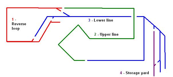
A tour of the line


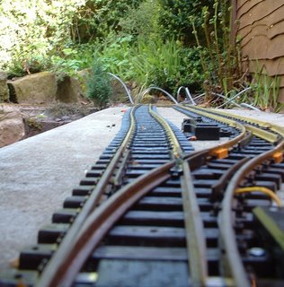
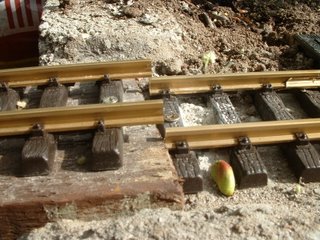
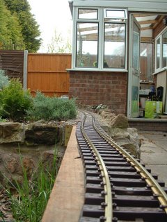
Emerging from the tunnel to the storage sidings we enter the main station. The run-round loop is completed (though not yet wired) and the siding to the right it to be laid. The base for the station is two 3'x2' paving slabs which so far have blunted three masonry bits. I will bide my time (and buy more masonry bits) before laying the final siding.

The station throat. All points are laid, but not yet wired up, hence the cables. Those screws need a dab of brown paint!

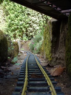
Through the underbridge which carries the upper line forming the figure of 8. This track is Aristocraft which has black sleepers and paler brass - but is a joy to lay as it is more flexible and resists springing back - but is apt to kink if you are not careful.

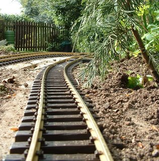
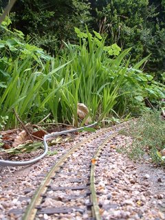
Rising up the incline (roughly 1 in 40) .......

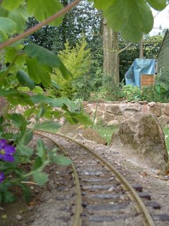
...... and around the rocky outcrop........

..... to the cross-over. The line to the right is used to reverse trains if needs-be.

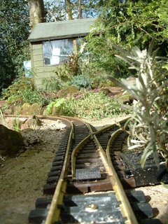
The line now curves to the left into the through station (yet to be named).

To the left is the siding and ahead is the cross-over for the passing-loop. You''ll notice a slight bow in the siding. Frustratingly the blocks have settled and there is a dip right under the pointwork which I now realise will have to be relaid. Past experience with OO gauge modelling has taught me that unless pointwork is perfectly level trouble will ensue!


Through the station - there will eventually be an island platform to the right. We're on LGB track here which is very robust but the 3m lengths can be somewhat unwieldy.

Looking back into the station ........


..... we then cross the long bridge. Incidentally, you'll notice the sun is shining - so it is now about 5 degrees warmer than when the track was laid - and already I am noticing the effects of temperature on rail expansion..............


The further rail is approximately 2mm longer now than when it was laid two days ago! A hacksaw job - and I will have to check all my expansion gaps again!

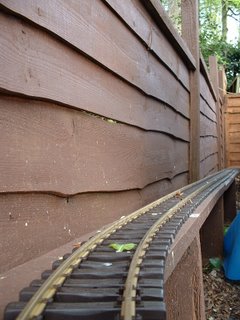
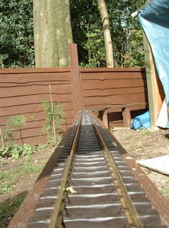
We now enter the non-scenic section behind the sheds. Interestingly, this seems to be the part which most interests visitors!

Back on to concrete blocks here.

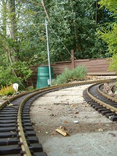
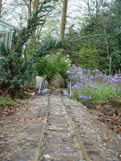
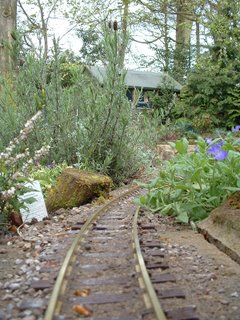
Through the conifers and back out into the garden. This section was meant to be 'hidden', but now the track has been laid I quite like it. I may remodel the approach so the trains can be seen snaking through the trees.


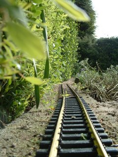
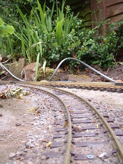
After traversing the cross-over, a gentle climb of 1:70 towards the overbridge crossing the lower line which is now on our right.

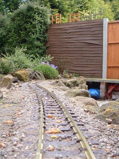
This is Tenmille track - which has a slightly narrower profile - more like bullhead than flat-bottom rail. It has been ballasted with 'Alpine pink' gravel held in place with exterior PVA adhesive. The wire to the left will soon be buried. It leads to the furthermost point for the through station.

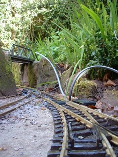
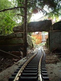
Looking back across the overbridge which crosses the lower line at the centre of the figure of 8. As the lines cross at an angle I needed a skewed bridge. The LGB girder bridge was sliced in half and skewed. I looks slightly drunken on the left - has yet to be fixed into place and cemented in.

The line now curves to the right. The terminus station is below to the left.


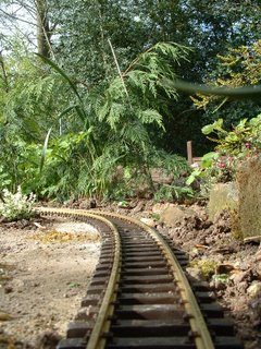
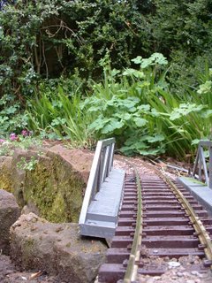
The line now descends (1:40). Ahead is the bridge over the stream which will later be extended into the area on the right. The ballasting here is a mix of gravel:sand:cement in the proportion 2:1:1. Brushed on dry and then watered. Much easier to lay than the PVA method and I must admit I am warming to its appearance. It doesn't look as artificial as the neat gravel and PVA method!

A curve to the right .........


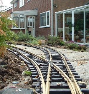
....before curving back to the left in a large circle. The through-station is across the lawn dead ahead at this point.


Across the patio bridge. To the left will be a small patio - eventually. Viewing the line from this level, I am alarmed to see how uneven the track seems to be. Some relaying might be required here otherwise there might be some interesting accidents as trains traverse the bridge!

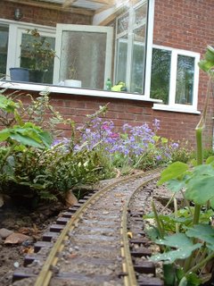
The line now meanders back towards the terminus station which can be seen ahead. I like this section of the line. I'm hoping that, once the vegetation becomes more established and the stream (to the left) flows through, on a summer's evening I can sit on the patio with a cool beer ......

We rejoin the railway at the terminus station to our right.
A test train has been run and already I have identified several 'snags' which need ironing out - mostly caused by the blocks settling. But there's plenty of time for that.............................


Monday, May 01, 2006

How did I do the electrics?

Sections
I have tried to keep the wiring as simple as possible, having only four sections:


  • The reverse loop and through station
  • The upper line from the crossover to the patio bridge
  • The lower line from the crossover to the patio bridge - also includes the terminus station
  • The storage yard
I will probably operate a simple service - no more than one or two locos 'in steam', hence having the option of being able to isolate one train while running another.
I thought long and hard about the reverse loop but decided it would be worth including it in the plan. I will thus be able to operate the layout as:
  • continuous loop
  • out-and-back (via the reverse loop)
  • and end-to end - using the through station as a terminus
The reverse loop will have a separate DPDT reverse switch to enable a train to run across the cross-over without causing a short circuit. However, this 'reversed' train will have to stop at the through station to have the polarity un-reversed.
I did contemplate using a diode bridge in the loop but as I will want trains to run in both directions around the loop had to reject it. For those who are unfamiliar with the diode bridge - four diodes are linked together:

This means that regardless of the polarity of the input from the controller, the output will remain unchanged. Thus, once the train is on the loop, the controller can be reversed and the train will continue in the same direction. If the controller is reversed quickly or via a reversing switch, the train will not appear to stop - though may hesitate slightly. As indicated above, because the polarity of the supply to the loop is fixed, dertermined by the diodes, trains can only travel in one direction around the loop.
Wiring
I have used domestic 1.5mm T/E (twin and earth) cable for the wiring. Once it situ, the cable will not be moved a great deal and hence does not need to be flexible. I also wanted something that would not lose to much voltage over the long runs in the garden. T/E cable has a single solid copper core rather than being multistranded; I felt solid cable would be less likely to deteriorate than multistrand over time.
Pointwork
I have opted for electrically operated points throughout. Initially, this decision was made for me as the LGB R3 points are only available as electrically operated versions. However, I decided that the extra wiring involved would ultimately be worthwhile as it will mean all points will be able to be operated centrally.

Where possible points are electrically linked. Hence, the two cross-over points are wired together so they will change simultaneously. This not only helps to prevent accidents, it saves on wiring - only one cable needs to be run from the control panel to the crossover.
Bonding
All rail-joints are bonded with soldered jumper leads.

A few years ago I invested in a 75 watt soldering iron and am very grateful for this decision. Once the iron has reached its operating temperature it is very easy to heat the rail to the right temperature. I intend to varnish all the soldered joints to prevent oxidisation.
From experience, I have two pieces of advice:
  • 1. Remember where you place the iron and try not to rest your hand on it!
  • 2. Make sure you pick up the iron by the handle !
I can testify (and show the scars) as to what happens if you ignore this guidance!
Control panel
The control panel has yet to be constructed - at present all wires end in an interesting cat's cradle in the lean-to. The intention is to create a switch-box which will control the four sections and the pointwork.