Sections
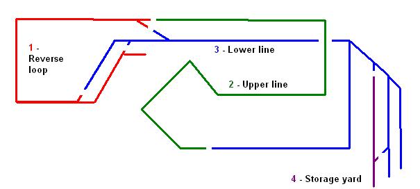
I have tried to keep the wiring as simple as possible, having only four sections:
I thought long and hard about the reverse loop but decided it would be worth including it in the plan. I will thus be able to operate the layout as:
I did contemplate using a diode bridge in the loop but as I will want trains to run in both directions around the loop had to reject it. For those who are unfamiliar with the diode bridge - four diodes are linked together:

This means that regardless of the polarity of the input from the controller, the output will remain unchanged. Thus, once the train is on the loop, the controller can be reversed and the train will continue in the same direction. If the controller is reversed quickly or via a reversing switch, the train will not appear to stop - though may hesitate slightly. As indicated above, because the polarity of the supply to the loop is fixed, dertermined by the diodes, trains can only travel in one direction around the loop.
Wiring
I have used domestic 1.5mm T/E (twin and earth) cable for the wiring. Once it situ, the cable will not be moved a great deal and hence does not need to be flexible. I also wanted something that would not lose to much voltage over the long runs in the garden. T/E cable has a single solid copper core rather than being multistranded; I felt solid cable would be less likely to deteriorate than multistrand over time.
Pointwork
I have opted for electrically operated points throughout. Initially, this decision was made for me as the LGB R3 points are only available as electrically operated versions. However, I decided that the extra wiring involved would ultimately be worthwhile as it will mean all points will be able to be operated centrally.

Where possible points are electrically linked. Hence, the two cross-over points are wired together so they will change simultaneously. This not only helps to prevent accidents, it saves on wiring - only one cable needs to be run from the control panel to the crossover.
Bonding
All rail-joints are bonded with soldered jumper leads.

A few years ago I invested in a 75 watt soldering iron and am very grateful for this decision. Once the iron has reached its operating temperature it is very easy to heat the rail to the right temperature. I intend to varnish all the soldered joints to prevent oxidisation.
From experience, I have two pieces of advice:
Control panel
The control panel has yet to be constructed - at present all wires end in an interesting cat's cradle in the lean-to. The intention is to create a switch-box which will control the four sections and the pointwork.
I have tried to keep the wiring as simple as possible, having only four sections:

- The reverse loop and through station
- The upper line from the crossover to the patio bridge
- The lower line from the crossover to the patio bridge - also includes the terminus station
- The storage yard
I thought long and hard about the reverse loop but decided it would be worth including it in the plan. I will thus be able to operate the layout as:
- continuous loop
- out-and-back (via the reverse loop)
- and end-to end - using the through station as a terminus
I did contemplate using a diode bridge in the loop but as I will want trains to run in both directions around the loop had to reject it. For those who are unfamiliar with the diode bridge - four diodes are linked together:

This means that regardless of the polarity of the input from the controller, the output will remain unchanged. Thus, once the train is on the loop, the controller can be reversed and the train will continue in the same direction. If the controller is reversed quickly or via a reversing switch, the train will not appear to stop - though may hesitate slightly. As indicated above, because the polarity of the supply to the loop is fixed, dertermined by the diodes, trains can only travel in one direction around the loop.
Wiring
I have used domestic 1.5mm T/E (twin and earth) cable for the wiring. Once it situ, the cable will not be moved a great deal and hence does not need to be flexible. I also wanted something that would not lose to much voltage over the long runs in the garden. T/E cable has a single solid copper core rather than being multistranded; I felt solid cable would be less likely to deteriorate than multistrand over time.
Pointwork
I have opted for electrically operated points throughout. Initially, this decision was made for me as the LGB R3 points are only available as electrically operated versions. However, I decided that the extra wiring involved would ultimately be worthwhile as it will mean all points will be able to be operated centrally.

Where possible points are electrically linked. Hence, the two cross-over points are wired together so they will change simultaneously. This not only helps to prevent accidents, it saves on wiring - only one cable needs to be run from the control panel to the crossover.
Bonding
All rail-joints are bonded with soldered jumper leads.

A few years ago I invested in a 75 watt soldering iron and am very grateful for this decision. Once the iron has reached its operating temperature it is very easy to heat the rail to the right temperature. I intend to varnish all the soldered joints to prevent oxidisation.
From experience, I have two pieces of advice:
- 1. Remember where you place the iron and try not to rest your hand on it!
- 2. Make sure you pick up the iron by the handle !
Control panel
The control panel has yet to be constructed - at present all wires end in an interesting cat's cradle in the lean-to. The intention is to create a switch-box which will control the four sections and the pointwork.
No comments:
Post a Comment