Introduction
The ubiquitous LGB/Playmobil 0-4-0 Toytrain chassis were (and to a large extent still are) the mainstay for many 45mm gauge kits and conversions. They formed the basis for the locos in basic starter sets - such as Otto:

OHO

and Rusty.

They are also used for the Playmobil diesel shunter.

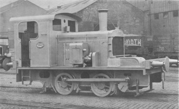
These chassis are quite basic in design but fairly robust and have the advantage that they do not have rubber traction tyres which are the bane of the Stainz and other 0-4-0 chassis. I have so far used two of these chassis as the basis for my kit-based conversions - see How I made a Peckett from a GRS kit and How I made a Hunslet from a GRS kit. I also intend to convert the Playmobil diesel into something more UK-based - such as this 1935 Fowler:
...... but that's another story (see How I converted a ToyTrain diesel into a Fowler(ish) loco).
Fitting the decoder
The first stage of of chipping the chassis was to strip down the donor loco to remove the body from the chassis. This was a fairly straightforward process, requiring the removal of half a dozen screws.
The next stage was to remove the cover holding the motor in place by removing two screws:
The cover lifts straight off to reveal the double ended motor.

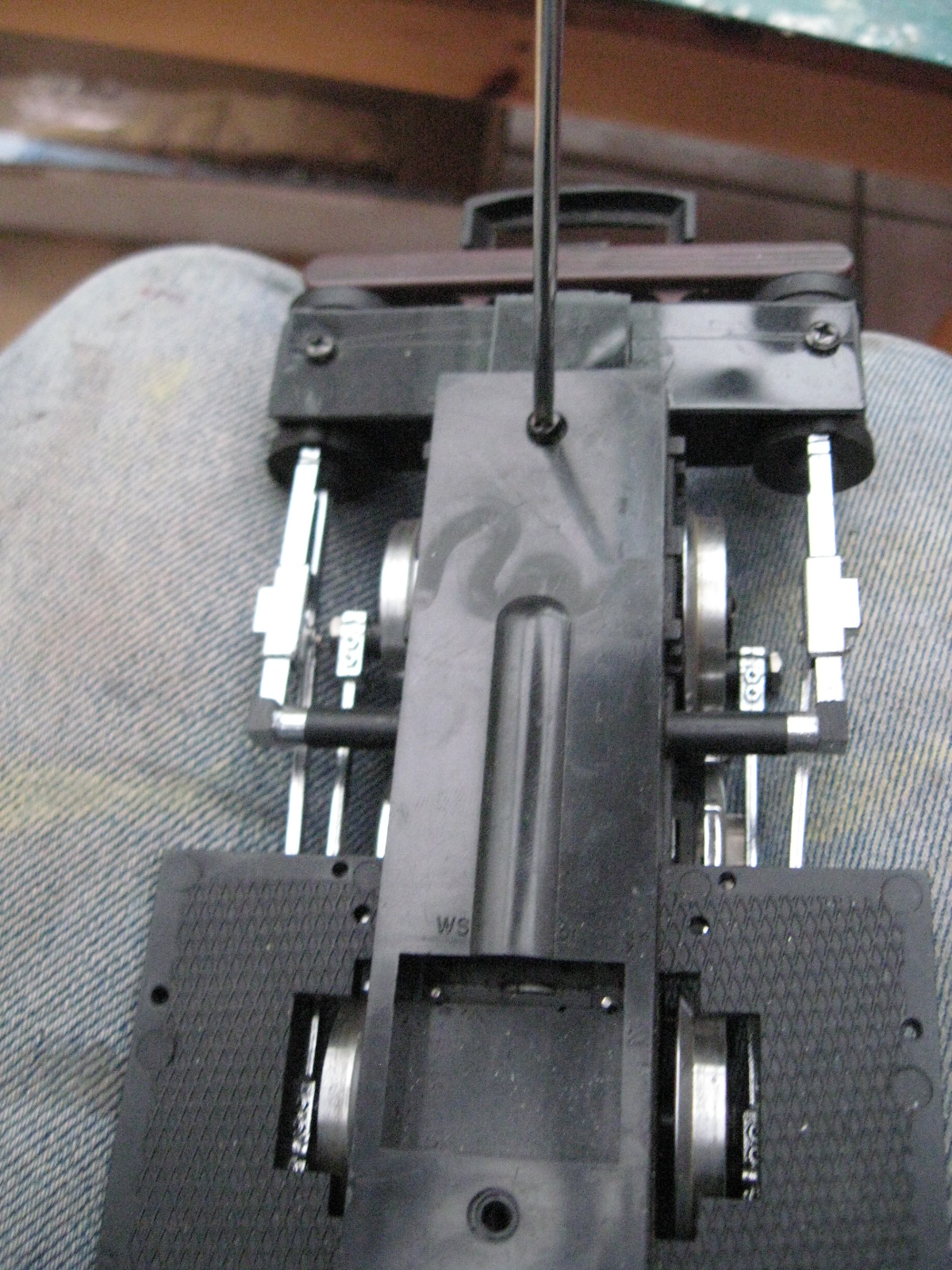
This simply lifts out. When fitting a decoder, it's important to isolate the motor connections from the pick-ups. This could be achieved by bending back the motor contact tags so they are no longer touching the vertical wire pegs which supply the current from the wheels and pick-ups. However, given the cost of decoders for G scale, I prefer something a little more reliable. I turn the motor around so the motor contacts have no chance of accidentally touching the leads from the pick-ups. To accommodate the motor contacts, a slot needed to be cut in the opposing chassis member. Two cuts were made on either side of the hole in the cross-member with a razor saw.

The plastic was removed by 'persuasion' from a pair of pointed-nose pliers. The hole in the chassis-member meant the plastic could be bent outwards until it snapped off. A needle file was used to do the final tidying up.

The motor was fitted back in temporarily to check clearances (Note the two pick-up wires now at the other end of the motor).

A similar slot needed to be cut into the flange on the motor cover, to provide sufficient clearance for the tag on the motor. Again, a razor saw was used.

Two holes were drilled in the other flange of the motor cover to take the leads from the motor contact tags to the decoder:

The decoder (a Massoth L or an LGB 55020 or 55021) was tucked into the boiler on each of my two conversions. The sockets were snipped off the ends of the motor leads (yellow and green)........

..... and the leads were then soldered to the motor tags after being threaded through the holes in the flange.

The motor cover was then screwed back into place, making sure the leads did not foul the motor mechanism, and the leads for the track pick-ups were pushed on to the pick-up connectors which protrude from the top of the motor cover.

The bodies of the locos were then carefully fixed back on to the chassis, making sure none of the leads were trapped in the process. The locos were then placed on the track, programmed and tested.