Thursday, December 27, 2012

Bickerton Copper Mine

A brief history of Bickerton Copper Mine

It is thought that copper has been mined at Bickerton and Gallantry Bank since the Bronze Age and by the Romans, but the earliest documented reference to mining in the area is in a report written by J D Brandshagen in 1697 for Sir Philip Egerton.  The sandstone outcrop at Peckforton forms part of the same geology as that of Alderley Edge, where there is also evidence of copper mining (See Copper Mining at Alderley Edge).
Alderley Edge Copper Mine: Source http://www.derbyscc.org.uk/caving/caving_image/JK_trip_20060507_21_resize.jpg
The seams of copper were worked intermittently until the 1860s though there was an optimistic survey carried out in 1906 in a bid to raise capital for a more extensive mining venture.
Today, there is very little evidence of the copper mining industry at Bickerton and Peckforton. It is possible to squirm into an abandoned adit in the hillside above the Bickerton Poacher pub, but the five main shafts to the deeper copper seam have long since been sealed. The remains of the chimney for the boiler serving the pumping engine above the main Engine Shaft can be seen from the A534 road.
The remains of the chimney beside the sealed Engine Shaft (Source: http://upload.wikimedia.org/wikipedia/commons/7/70/Copper_mine_chimney_-_geograph.org.uk_-_713124.jpg)
I have been unable to find any drawings or photos of the copper mine when it was operational, the earliest I've been able to discover shows it in a derelict state taken at the beginning of the 20th century:
Bickerton Cooper Mine circa 1904 (Source: http://www.sandstonetrail.com/wp-content/uploads/Coppermine.jpg)

 The mines

 Although Shaft No. 5 and the Pit were shown in an 1890 survey of the mine workings (Edwards, 1890), only the Engine Shaft and Shafts 1, 2, 3 and 4 are shown in the 1906 survey (Spargo & Thomas, 1906) suggesting these were the only workable shafts at that time. This drawing shows the approximate position and extent of the workings based on these two surveys (click on the image to enlarge).
Bickerton Copper Mine (Based on Carlon (1981) Fig vii)
The Engine Shaft was the deepest, at 156 feet, No. 1 shaft was around 60 feet deep, No. 2 shaft was 35 feet deep, No. 3 shaft was around 110-120 feet deep, shaft No. 4 was somewhere between 117 and 135 deep while shaft no. 5 was 65-70 feet deep. As the the ore zone was inclined at an angle of approximately 80 degrees to the vertical, various levels and stopes needed to be worked from the shafts to access the ore. Shafts No. 4 and 5 were the oldest, and were worked until the beginning of the 19th century. Only Shaft 3 continued working after the mid 1800s. The pit between shafts 4 and 5 was later used as a well.

It is assumed that the mine shafts at Bickerton were relatively dry as the pumping engine over the Engine Shaft was a modest affair. Over the years, advice had been sought from Cornish mining engineers and so it is highly likely that the mining practices at Bickerton would have been heavily influenced by those carried out in Cornwall.
The type of pumping engine house possibly used at Bickerton (Source: http://farm5.static.flickr.com/4079/4798065476_e74ec2c1ee.jpg)
As the main shaft used for the extraction of ore was Shaft No.3 it must be assumed there was some sort of winding engine situated nearby, though this is not documented in any of the sources consulted.
Steam powered winding engine used in copper mine (Source http://s0.geograph.org.uk/geophotos/02/32/38/2323827_775bb0fa.jpg)
Through the 18th and 19th centuries various schemes were put into effect to develop the mine but by the turn of the 19th century, the mine had been left unworked for around 35 years. Edmund Spargo's survey of 1906 concluded that by widening and deepening the main shafts the mine could easily be expected to yield around 18000 tons of copper which would net a profit of around £1.1m (equivalent to around £115m today)! The Bickerton Copper Mines Syndicate Ltd. leased the mines for three years in 1907 but seem to have carried out very little work and was dissolved in 1911. In 1917, UK Minerals Development took out a three year lease of the mine but again very little work took place. During the 1920s, three local men worked No. 3 shaft intermittently using a bucket, rope and hand winch and unearthed some rich pieces of bright blue crystalline azurite.
Azurite and malachite (Source: http://upload.wikimedia.org/wikipedia/commons/9/97/Azurite-Malachite-59275.jpg)
By the 1930s the mines gradually fell into decay until the shafts were filled and sealed in the 1960s and what remained of the mine buildings were demolished in a road widening scheme in 1977.

 The minerals

There were two veins of copper-bearing rock in the mine at Bickerton which varied in width from eight inches to five feet, with an average of 2½ feet. There was also thought to be cobalt, lead and silver deposits in the seams. In 1802 a sample of ore from Bickerton was sent to the Mineralogical Society for analysis which pronounced there was 9% copper in the sample in the form of copper sulphide and copper carbonate. However, another analysis in 1806 found the ore varied in quality from 0% to 2½%, whereas another in 1862 found there was between 19¼% and 25% of copper and 18 ounces of silver per ton of ore.

The minerals present in the ore were malachite and principally azurite, though there were also traces of chrysocolla, melaconite, bornite and covellite. These were deposited in an almost vertical fissure of white sandstone, similar to that found at Alderley Edge, Clive, Pim Hill, Whixall and Eardiston.
Mineralised sandstone from Alderley Edge (Source: Minerals UK)

 The copper mining process

Until the middle of the 19th century, copper was extracted and processed mainly by hand, but thereafter mechanisation played an increasing role. By the early 1930s, when my model is set, pneumatic and hydraulic mining equipment would have been used, though this would also have been supplemented by hand tools and the use of explosives. As the shafts and galleries were very narrow, it seems reasonable that the narrowest gauge of railway would have been used to transport the ore and spoil beneath the ground. Railway tracks were found in the mines at Alderley Edge - though these are associated with later restoration work.
Copper Mines at Alderley Edge (Source: http://www.mine-explorer.co.uk/photo_cache/mines/Alderley-edge_2547/Alderley-edge_22468.jpg)
By contrast, in the Parys Mine in Anglesey there were no underground railways in the copper mine owing to the corrosive effects of contaminated water on the equipment (see Parys Underground Group - Railways). As we have seen above, the mines at Alderley Edge and Bickerton were relatively dry and it is more likely they would have used underground railway trucks to transport the ore and spoil if the mines had been further developed.
Tub from the Saint Veran Copper Mine in France (Source http://www.aditnow.co.uk/photo/Personal-Album-1-Image-067)
Once extracted from the mine the ore was crushed and then ground before the copper-bearing minerals were further extracted using an oil flotation process where the impurities rose to the surface and were skimmed off. The ore would then be smelted and refined.
Copper Processing (Source: www.bgs.ac.uk/downloads/start.cfm?id=1410)
 Once the ore had been removed from the mine and crushed, any rock which held more than 5% of copper could be sent directly to the smelters while any below that could be treated using the wet acid process which would produce copper sulphate (used as a crop spray).

The (fictional) history of the Peckforton Light Railway

To provide my 16mm scale garden railway with a realistic context, I have made some hypothetical propositions and just a few flights of fancy. However, where possible, these have been based on facts and reflect what might have happened, given the certain favourable conditions. My fictional inventions are shown in italics, the rest is factual.

In my imagined history (see A History of the Railway), the local landowner, Lord Tollemache, decided to invest in the copper mines following the optimistic report produced in 1906 by Spargo and Thomas. As a consequence built a three foot gauge railway to transport the mined ore and spoil to the mainline Crewe to Chester railway via the former Beeston & Tarporley Station. Bentley Tollemache succeeded his father, Wilbraham, as the 3rd Baron Tollemache in 1904 and as such became the owner of the Peckforton Estate which included Peckforton Castle. Peckforton Castle was built in the middle of the nineteenth century by his grandfather, John Tollemache (see History of Peckforton Castle). It was designed in the Gothic style by the architect Anthony Salvin and was described in 1858 by Sir George Gilbert Scott, the architect of St Pancras Station, as "the largest and most carefully and learnedly executed Gothic mansion of the present."
Peckforton Castle shortly after completion in 1851 (Source: http://www.dicamillocompanion.com/images/Houses/database/Peckforton_Castle.jpg)
Bentley Tollemache was actually a keen amateur engineer and I like to imagine that, as a consequence, he would have been very enthusiastic about constructing a narrow gauge railway to serve his pet project, the mining of copper on the edge of his estate. I also hypothesise that he would have constructed a 15" minimum gauge railway to handle freight within his estate, inspired by that constructed by his near neighbour, the Duke of Westminster at Eaton Hall (see Eaton Railway) and influenced by the work of Sir Arthur Heywood (see Historical Background to Minimum Gauge Railways)
Source: http://www.eatonestate.co.uk/NR/rdonlyres/914E2056-B26C-4216-9DD2-3E2E28C8E274/8142/Katie.jpg
I am assuming that as the ores were relatively copper-rich at Bickerton (if Spargo & Thomas are to be believed), once extracted from the mine they would then crushed before being loaded into wagons for transhipment to be processed and smelted elsewhere - maybe near the sister mines at Alderley Edge. I am also assuming that Lord Tollemache was a canny businessman and that he would have identified a ready market for the non-copper-bearing spoil. The sea defences along the Dee Estuary were being reinforced during the period in which my model is set and hence there would have been a call for crushed rock and rubble from a range of sources.
The Dee Estuary (Source: http://www.gutenberg.org/files/29787/29787-h/images/p033.jpg)
 My model of the mine assumes that more than one shaft would have been enlarged to allow for the mechanical extraction of the copper ores. Furthermore, additional shafts will have been sunk along the ore line to gain access to other rich deposits of copper-bearing ores. These shafts would have been interlinked at the surface by a 15" minimum gauge railway using internal combustion powered locomotives. Rock from the workings would be transported to the crushing and sorting machinery housed in sheds adjacent to the pumping engine and old mine workings beside the Engine Shaft. The pumping engine would have been updated, but remained steam driven, whereas the crushing, sorting and conveyor mechanisms would have been powered by diesel engines.
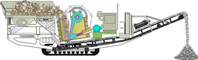
Ore crusher (Source: http://www.bricscrushingplant.com/images/solutions/gen/36.jpg)
 Although the image above shows a modern mobile ore crusher, the technology has not changed radically over the years and a similar, albeit stationary, system of crushing would have been in use in the 1930s. The ore is loaded into a hopper on the left and is fed into the crusher mechanism, which crushes the ore between fixed and movable jaws. The crushed ore is then conveyed to a loading hopper (see How I constructed a wooden loading hopper).

By 1932, when my model is set, I'm assuming that the viably workable seams were becoming exhausted and so there was proportionately more spoil being extracted than copper ore. As a consequence, there was less money available for carrying out repairs and the railway and the works were beginning to fall into decay. However, the tourist potential of the area was becoming more lucrative as the healing powers of the mineral waters in the Peckforton Hills were being exploited and the largely unspoilt scenery around Beeston and Peckforton Castles proved attractive for Bank Holiday visitors from Manchester and Birmingham.

Bibliography

  • C.J. Carlon. (1981) British Mining No.16:- The Gallantry Bank Copper Mine, Bickerton, Cheshire
  • H. Dewey. T. Eastwood. (1921) MGS Special Reports, Vol. XXX: Copper ores of the Midlands

Monday, December 24, 2012

Progress Report 44

At this time of year I tend to find that railway maintenance and development goes into tick-over. Rather than becoming immersed in a grand project, I am more inclined to tinker with several ongoing tasks. The major project on hand at the moment is the construction of buildings for the copper mine which are taking up quite a bit of space in the conservatory which I also use as a workshop. The sheer size of these structures means that each job takes some considerable time. There is also a fair degree of waiting between jobs as glue, paint or filler dries and/or hardens. During these interludes, I usually turn to other jobs - some of which I regret to say have to be non railway-related. Since the last progress report I have, however, engaged in a few other activities - constructing a wooden loading hopper from a kit, sculpting some figures in oven-hardening polymer clay and purchasing a kit for a battery-powered diesel outline loco.

Mine buildings - update

Since the last progress report I have grouted and started painting the stonework to more closely resemble the local sandstone. I experimented with various sorts of grouting and eventually opted for a mix of cream and brown tinted waterproof grout which was left over from a couple of household tiling jobs. The grouting not only fills the gaps between the blocks, it also gives them a bit more texture.

The corrugated iron sheets have been given a couple of coats of red 'oxide' primer and a start has been made on weathering them using acrylic paints and Scenic Rust which I used successfully to weather the tippler wagons (see How I weathered some LGB tippler wagons).

Originally, I cut down some 32mm gauge SM32 track to 16.5mm gauge for the minimum gauge feeder line, but this looked over scale. I have since bought some Peco 0-16.5 'crazy' track and although this is under scale, it more closely resembles the sort of lightweight rail which would have been used for a minimum gauge mine railway.

One day I aim to build and indoor Gn15 railway to maybe represent the imagined estate railway which my hypothetical history suggests would have been constructed at Peckforton Castle by Lord Tollemache, after having been inspired by his near neighbour's line at Eaton Hall (see A short history of the railway). As you can see, I have accumulated a few items of rolling stock over the past few years. My visits to various minimum gauge railways across the UK has made me become a lot more aware their history and the influence of Sir Arthur Heywood and Henry Greenly (eg see The Perrygrove Railway).

Loading hopper

A chance find on eBay led to the purchase of a prefabricated German wooden kit for a loading hopper. I had always intended to construct a set of wood and steel loading hoppers for the copper mine and this kit has somewhat short-cut the process.

The hopper will eventually be located over the track leading from the copper mine to the exchange siding at Beeston Market (see The Copper Mine - pending) but as this will require some widening of the timber trackbase the hopper was temporarily sited on the timber yard siding at Peckforton for the photo shoot.

There is still some detailing and light weathering to be completed on the model but for now I am pleased with the outcome (see How I constructed a loading hopper)

Bespoke figures

I have been trying for some time to find appropriate figures in various poses to make a few small tableaux on my railway without success. I have found with commerical figures that either the poses are not what I want or the clothing is not appropriate for an English narrow gauge railway set in the early 1930s. After an abortive attempt to construct my own figures from polymer clay (see Creating atmosphere - Progress Report 31), I consulted various sources on the internet and have been improving my skills. I certainly can't claim to be a Rodin, a Henry Moore or an Antony Gormley but my figures are slowly beginning to resemble something vaguely human.

[Awaiting photo]

The knack seems to be getting the proportions right in the early stages and then having considerable patience and time to sculpt features and details. I have found this is the sort of job I can do while 'watching' TV in the warmth of the living room on these cold and dark winter evenings.
Once I have perfected my techniques to what I consider to be a reasonable standard, I will share my results via another posting (see How I sculpted some figures from polymer clay - pending). However, this might be some time in the future, given my slow rate of progress so far.

Diesel loco kit

Another chance purchase through the G Scale Central forum resulted in the arrival of a 'Jessie' diesel locomotive kit made by IP Engineering.
Source: http://img36.imageshack.us/img36/6893/bt7wmmkkgrhgoheyejllly8.jpg
As this kit is no longer listed on the IP Engineering website I assume it is discontinued. However, the kit I purchased seems to be complete and also includes various additional detailing parts. Once completed this loco will be added to the slowly growing roster of battery-powered locos which I am accumulating (eg see How I constructed a railmotor). My ultimate plan is to have a complete set of locos for both DCC and battery power to hopefully extend the opportunities for operating sessions through the year as the track cleaning process required for track power can become tedious prior to a brief operating session (see How I clean the track).

Tuesday, December 18, 2012

How I constructed a loading hopper

The copper mine is an important feature of the railway as it was the supposed reason for the line's existence. I recently started construction of some low-relief mine buildings (See How I constructed some low relief buildings for the copper mine - pending) and had planned to scratchbuild a loading hopper, but I happened to come across a wooden kit by the German company of Holzmodellbausatz  on a well known internet auction site.


The kit contained all the pieces needed, most of them pre-cut, and an exploded diagram with some instructions in German.

Although the exploded diagram was well detailed, my lack of ability to read German meant I had no indication as to the order in which the pieces should be assembled. I decided that as the hopper looked to be the most substantial part of the model, I would start with that. The four pieces of ply were glued with exterior PVA and tacked together with copper panel pins.

The four pieces forming the upper part of the hopper were then assembled and glued to the lower section.

Next, the internal sloping pieces for the hopper were glued into place.

The main structure of the hopper was completed and so this was left overnight for the glue to harden. The next most obvious components to be tackled seemed to be the legs. These comprised four pieces of 8mm square stripwood, 336mm in length. There were tacked and glued to the sides of the hopper.

To these were glued the platforms on either side of the hopper, with lengths of stripwood glued and tacked on to keep them aligned with each other.

The side platforms were grooved to allow a door to slide beneath the hopper to control the flow of rocks etc.. I decided not to construct this as operational as the fairly basic mechanism looked to be more functional than realistic.

The struts for the legs were then glued into place - two per leg.

Although I have a fair amount of confidence in PVA as a wood glue, I was not too sure about the bond between the struts and the legs and the rest of the structure. Short pegs from cocktail sticks were inserted into suitably drilled holes ........

....... before the supports for the legs and struts were glued into place on the foundation blocks.
 Pegs were also used to keep some of the other timbers aligned and in place. These were trimmed and sanded smooth once the glue had set.

The main framework members around the hopper were then glued into place. Initially I concentrated on the more substantial 8mm square members.

The 8mm x 8mm cross members for the legs were then pegged and glued into place.

 I then focused on the 3mm x 8mm framework sections, which needed to be trimmed to size. I decided not to follow the exploded diagram and so placed the timbers where I thought they looked most at home. I also took the opportunity to use them to disguise the join between the sides and the ends of the hopper.

 The main structure for the hopper was now complete.

At this point I decided to treat the wood, using a spirit-based wood preservative (Cuprinol). The stripwood was clearly pine and I had no idea as to whether the plywood was exterior grade and so I decided to take no chances. I flooded the exposed woodwork with two generous coats of preservative and then touched-up any areas which had not absorbed the preservative (ie those already covered with PVA glue) with a muddy mix of  acryclic paint.

Whilst this was drying off, I cut the pieces needed for railings. In the kit, these were supposed to be made from various pieces of stripwood, but to my mind they looked too heavyweight. I decided solder together some metal railings from pieces of brass rod and 00 code 100 nickel silver rail. Firstly, four 6cm long pieces of 00 rail were cut and drilled to take the bars of the railings.

These were then slotted into place in suitably drilled holes and 1.2mm diameter brass rods were threaded through the holes and soldered into place.

The railings were then removed and given a couple of coats of grey primer and a coat of matt black paint.

The railings were then fixed back in place with some epoxy resin to hold the uprights firmly in the holes. A ladder left over from my construction of semaphore signals (see How I constructed semaphore signals - pending) was then cut to length. The legs of the safety hoop were inserted into suitably drilled holes in the side of the platform .........

.............. and a piece of stripwood was fixed to the base of one leg, to which the ladder was attached with a couple of loops fashioned from brass rod.

At this point I decided the main structure for the hopper was complete - though in the future I intend to construct a representation of some sort of operating mechanism for the doors.

I tried siting the hopper in its intended location at the copper mine but some additional foundation work will be needed to widen the raised timber trackbed on which it sits. In the meantime I temporarily positioned the hopper on the timber siding at Peckforton Station for a quick photoshoot.


I am considering weathering the hopper - blanching the timbers slightly and depositing layers of rock dust in the nooks and crannies. However, I am postponing this until I finish the mine buildings which are presently under construction (see Progress Report 43). Ultimately, the hopper will be connected to the mine buildings via some sort of conveyor to supposedly take the copper ore from the base of the crusher up to the hopper (see How I constructed some mine buildings - pending). The actual design of this will be dependent on the relative positions of the hopper and the building housing the crusher.

Saturday, November 24, 2012

Managing freight on the railway

One of the greatest pleasures I gain from running the railway is the handling of freight operations. To my mind, the sight of a mixed goods train winding its way through the greenery in the garden is far more evocative than watching a passenger train.

 In addition, I enjoy the logistical problems of shunting goods wagons to form realistically configured freight trains.


Operating sessions

Operating sessions centre on the running of a daily timetable which is based heavily on the 1923 timetable for the Southwold Railway.

Interspersed with this passenger timetable is a daily pick-up goods which sets out in the morning from Beeston Market, wends its way along the line dropping-off and picking up wagons, and then returns in the afternoon. The first passenger train of the day includes a flat wagon which picks up milk churns from halts and stations along the way .........

 ........ and the last train of the day is sometimes a mixed train, dependent on need.

 The goods traffic for the railway is generated by a relational database computer program which keeps track of the location of each wagon and generates trains in a semi-randomised way, based on percentage weighted traffic movements (ie the % likelihood that a particular wagon will travel from one station to another on the railway (see Computerised freight operation).

Traffic between the copper mines and the transshipment siding at Beeston Market is slotted-in between the above workings - usually running to three or four trains a day up and down the line.


Working out freight traffic needs

Over the years I have acquired and constructed a range of goods vehicles to handle the freight traffic on the line. The types and number of wagons on the railway have been determined by considering the needs of the local community. As the Peckforton Light Railway is hypothetically located in the rural countryside of Cheshire, the goods carried on the railway comprises coal, agricultural equipment, milk and cheese, soft fruit, livestock, building materials and general merchandise such as supplies for local stores and public houses (see Progress Report 12). In addition, there is a timber yard at Peckforton and, of course, the copper mines which form the main raison d'etre for the railway, both of which generate regular traffic. The mines not only require the transshipment of crushed copper ore and spoil from the workings to be transported as land-fill for sea-defences on the Dee Estuary, there is also a regular requirement for fuel oil, coal and explosives.

To cater for these needs, the railway has acquired 18 open wagons with coal and mixed loads.

The majority of these have been constructed from my own resin castings mounted on Hartland wagon chassis (see How I constructed my third batch of open wagons).

In addition, there are timber wagons,

a couple of tanker wagons (see Anglicising LGB tanker wagons),

 cattle wagons (see How I constructed cattle wagons from plasticard),

flat wagons (see How I created some flat wagons and Progress Report 39).

and closed vans (see How I converted an LGB Balcony van into a closed van).

There are also two rakes of weathered ore tipplers, one fully loaded and the other empty (see How I created loads for tipplers - and - Weathering tippler wagons).

Most of the open wagons and flat wagons have removable loads so the wagons can run fully laden in one direction and as empties in the reverse direction (see Progress Report 39). For more information see the railway's stock list.


Meeting those needs

At the start of a running session, my first job is to check the timetable to see where I had reached in the previous session. In an ideal world, each operating session would see the day's timetable run through in its entirety. In reality, I seldom manage a complete day's operation in a session and so have to leave off operations and then pick them up again at the start of the next session.

To assist in the above process, every siding on the railway has its own stock-box. At then end of an operating session the stock is rolled into its relevant box and the boxes are stored to be taken out again at the start of the next session (see How I made some stock boxes).

Locos and passenger stock are then restored to their previous locations and then, if the pick-up goods or mixed train is likely to be run in the session, the computerised freight program is fired-up to generate the day's freight traffic movements, and printed-out (see Computerised freight operation)..

Once the track has been cleaned, the next train of the day is run (see Track cleaning).

I get a great deal of satisfaction from conducting shunting operations - should that wagon be picked-up or dropped-off as the pick-up goods travels down the line or on its return-journey? How can I ensure the loaded cattle wagon is marshalled adjacent to the loco to avoid too much jostling of the livestock? How do I ensure the tanker wagon is marshalled as far as possible away from the loco? etc. (see Shunting Puzzles website)

From time to time I insert a special goods train. As its name suggests, at Beeston Market there is a Smithfield market adjacent to the station - much the same as Welshpool station on the Welshpool and Llanfair Light Railway.
The Countess at Welshpool Market - source: http://www.classictransportpictures.co.uk/photo_9955662.html
 What better reason to run a market day special in which all the livestock wagons, some of the flat wagons with agricultural machinery, a couple of vans containing produce and a workman's coach for the farm-hands accompanying the livestock?

Or, once in a while, a special coal train is run - assuming supplies need urgent replenishment following a national strike.

One of the greatest joys of garden railway modelling is that it can cater for all tastes. There are those who like to see trains running around the garden behind a live steam loco, those who enjoy seeing scale length express trains running at speed along a representation of a main line, those who want to display their collection of pristine rolling-stock and those who want to recreate a representation of a railway run more or less on prototypical practices. Whilst there are flaws in my approach, what is more important to my mind is the pleasure which I derive from playing trains.