You will see from Progress Report 39 that there was a list of jobs which needed to be carried out over the winter months. Many of these have now been completed (see also Progress Report 40)
Maintenance jobs
Repair Hunslet loco and add more weight
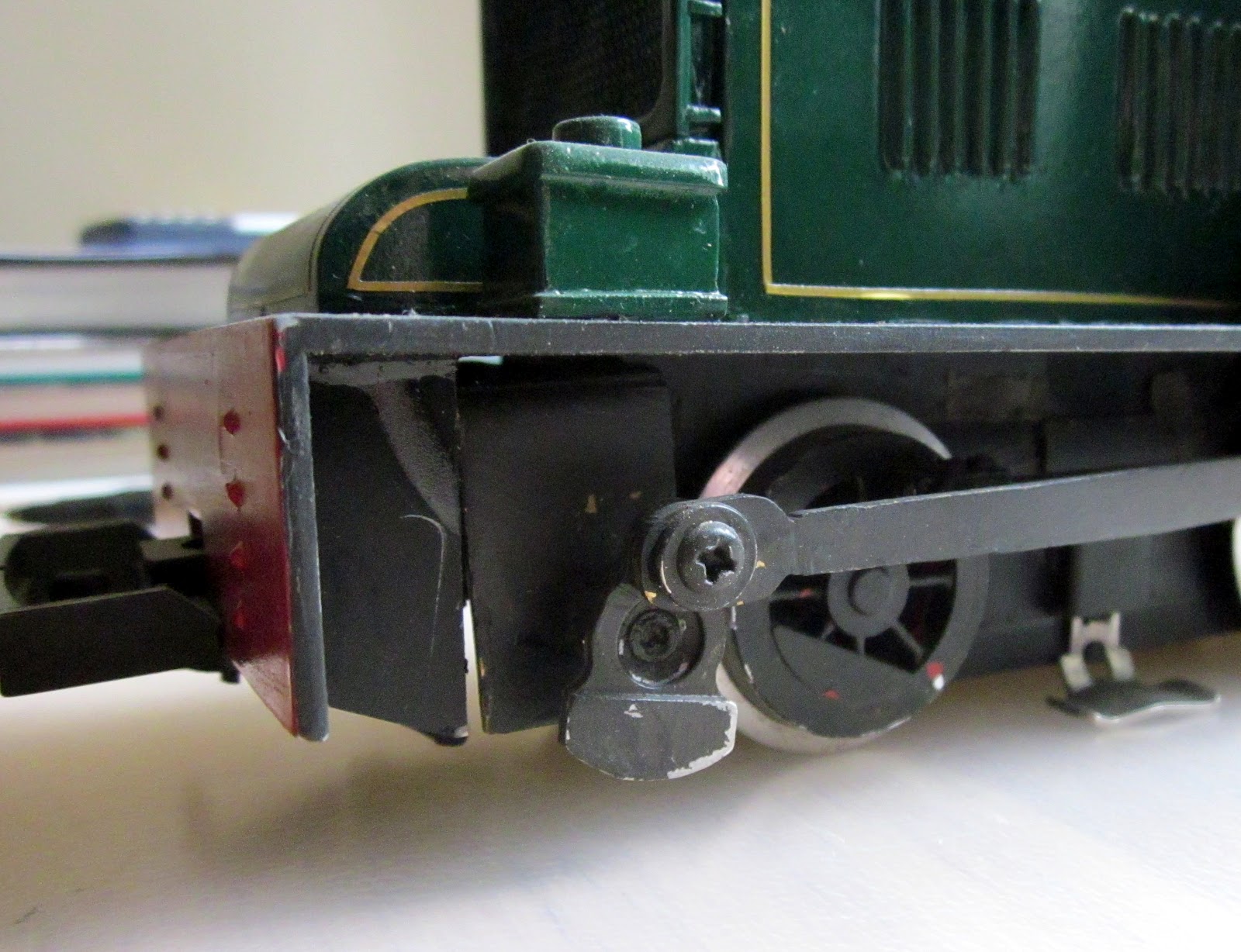
After having a power-buffer fitted, the Hunslet has never quite been the same. Some of the lead had to be removed to make room for the buffer and as a consequence the loco lacked adhesion when pulling some trains up the gradients on the line. More lead has been squeezed into the loco by filling as many nooks and crannies as possible. Also, the joints have been reinforced with good quality cyanoacrylate superglue as the rapid epoxy used previously seems to have failed.
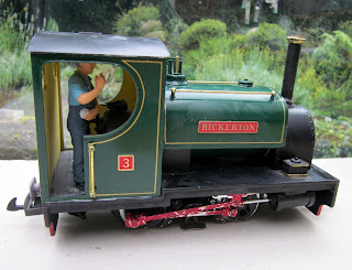 Unfortunately, the paintwork has suffered with a few smeary finger-marks and cracking around the failed joints. I'm going to have to try some remedial work, otherwise she will have to return to the paint-shops for a complete respray.

Fix Fowler diesel fly-cranks which have become loose on layshaft
The whitemetal fly-cranks were originally fixed to the steel axles with superglue and after a while have a tendency to work loose. In an effort to improve the bond between crank and shaft, I removed the cranks, roughened-up the ends of the shaft with a coarse file and fixed them back in place with epoxy. Time will tell if this is effective. If not, my next strategy will be to use larger gauge steel for the shafts, square off the ends and similarly file the holes square in the cranks.

Clean coach wheels and check bogies through pointwork at Beeston Castle
The IP Engineering steel wheels which I use for the coach bogies seem very prone to gathering accumulated gunk if I run them when the track is slightly damp. The gunk hardens to form an irregular layer on the treads of the wheels causing the coaches to limp unevenly along the line and derail over pointwork - particularly that at Beeston Castle which is slightly uneven.

I've tried smoothing out the irregularities in the trackwork so now the vast majority of stock runs through the pointwork without issue, but the coaching stock still occasionally runs into problems. The coach wheels were removed from their bogies and mounted in the chuck of a battery-powered drill which in turn was clamped in a vice. The wheels were then spun in the drill and cleaned of dried gunk using a flat-bladed screwdriver.


I've tried smoothing out the irregularities in the trackwork so now the vast majority of stock runs through the pointwork without issue, but the coaching stock still occasionally runs into problems. The coach wheels were removed from their bogies and mounted in the chuck of a battery-powered drill which in turn was clamped in a vice. The wheels were then spun in the drill and cleaned of dried gunk using a flat-bladed screwdriver.

Replace IP Engineering cattle truck metal roofs with plastic to reduce weight
New roofs for the two IP Engineering cattle trucks were constructed from plastic roofing sections (Part No. SG1109) provided by Garden Railway Specialists (GRS).

The moulded roof supports provided with the roof sections were fixed in place on underside of each roof to provide a sung-fit and then the roofs were given a couple of coats of my acrylic roof-colour (black mixed with silver). As above, this reduction in weight has enhanced the locos' ability to pull the wagons up the gradients.

The moulded roof supports provided with the roof sections were fixed in place on underside of each roof to provide a sung-fit and then the roofs were given a couple of coats of my acrylic roof-colour (black mixed with silver). As above, this reduction in weight has enhanced the locos' ability to pull the wagons up the gradients.
Repair hinges on engine shed doors
You will see from the original engine shed posting (see How I built the engine shed) that the hinges were fashioned from brass sheet and epoxied to the doors. Unfortunately the bond between the brass and the doors was never sufficient to take the strain and so, after several abortive attempts at gluing, the hinges were removed and fixed more permanently in place by drilling holes in the brass and passing dress-making pins through them into the underlying wood of the doors. This approach, together with superglue, will hopefully prove more enduring.


Construction jobs
Complete rail-motors/railbuses
These have now been completed (See How I constructed a Railmotor set) though the motor/gearbox arrangement on the motor-coach has proven to be insufficient to power the two coaches.
The IP Engineering gearbox which was used reduces the drive by only 16:1 which means that even on 12 volts the motor coach is under-powered. I am presently toying with three alternatives to resolve the problem:
- rebuild the motor/gearbox with a greater speed reduction (eg a two-stage gearbox drive)
- add a motor to the trailer coach
- build a powered luggage van to sit between the two coaches, using a power bogie.
The first option would be the cheapest, but may require the motor coach to be dismantled and rebuilt to accommodate a bigger gearbox. The second option would be relatively straightforward but I am concerned that even then the railbus set will be under-powered. The third option would be less disruptive to the existing construction, but will be the most costly.
Construct gunpowder van
A kit for a corrugated van was purchased from Swift Sixteen after seeing them on the stand at the annual show for the Association of 16mm Narrow Gauge Modellers. I decided a metal-bodied van would be the most likely candidate for conversion to a gunpowder van. This how now been completed and has joined the rolling stock roster - see How I constructed a corrugated van from a Swift Sixteen kit.


Construct another five open wagons
The Hartland wagon chassis for these have been purchased from Steve Warrington at Back2Bay6 as has the resin needed for the castings which was bought from TOMPS. These are in the course of construction and will be joining the wagon fleet during the summer months (see How I made the third batch of open wagons). In the meantime, two more LGB/GRS open wagon conversions (see Constructing an open wagon and a van from a GRS combi-kit) have been purchased over the internet and are awaiting a trip to the paint-shop.

These came as part of a job-lot with an Atropos Admiralty flat wagon which I am uncertain about using. I think I'll try attaching it to the first passenger train of the day to pick up milk churns.


These came as part of a job-lot with an Atropos Admiralty flat wagon which I am uncertain about using. I think I'll try attaching it to the first passenger train of the day to pick up milk churns.

Construct crane wagon (maybe mount a yard crane on a Hartland chassis)
A rash purchase on eBay resulted in the arrival of an LGB crane wagon.

Looking more closely at this I've decided it does not really represent the sort of wagon which would be seen on a UK narrow gauge railway and as a consequence have constructed my own. See How I constructed a crane wagon.

Looking more closely at this I've decided it does not really represent the sort of wagon which would be seen on a UK narrow gauge railway and as a consequence have constructed my own. See How I constructed a crane wagon.

Finish painting remaining figures
With the exception of a few instances of minor detailing, all the figures which have been purchased for the railway have now been painted and in some cases modified to make them suitable for the railway. In the last update I suggested that there were too few railway staff in evidence. This has now been remedied and so each of the guards' vans now boasts a guard. and each station has a least one station porter-cum-station-master. The locos now have drivers (including the railmotor which has a driver at each end - one of which was formerly a pall-bearer). The coaches have passengers and there are now sufficient members of the public to populate the station platforms. As has been mentioned previously, all standing passengers have brass rods inserted in at least one of their legs to enable them to be positioned upright on the platforms which, in the case of concrete platforms, have mounting holes provided by rawlplugs.


In addition, I purchased a secondhand model of a steam wagon made from a Model Town kit. The paint job on this is a little basic and I'd like to improve this and add some detailing on the model before deploying it.

A local fruit grower (Bellis Brothers) used to transport their produce to the local railway station using steam wagons, so I feel there is a local precedent to justify the use of this type of wagon.


Detailing for stations
I am slowly accumulating general clutter to adorn station platforms. To date this includes a few suitcases, a porter's truck and some seating. However, I need to make or acquire more luggage, boxes and crates and other items such as vending and weighing machines. I may try casting some of these from resin.Period vehicles
I have purchased three horse drawn vehicles from various sources, I'm constructing a brewer's dray from a kit and have a Hobbies kit of a horse drawn coal wagon awaiting construction. The wagons will be positioned on station forecourts or on the road crossing the overbridges during operating sessions to provide some wayside interest.
In addition, I purchased a secondhand model of a steam wagon made from a Model Town kit. The paint job on this is a little basic and I'd like to improve this and add some detailing on the model before deploying it.

A local fruit grower (Bellis Brothers) used to transport their produce to the local railway station using steam wagons, so I feel there is a local precedent to justify the use of this type of wagon.

Jobs which were on the 'possible' list
Re-site copper mine further back from the main line and ease the R1 main line curves
I've decided that this will be a job for net winter. Owing to family commitments there was insufficient time for this somewhat major project. In the meantime, I intend to construct some buildings modelled in half-relief to represent various workshops and mine buildings - including that housing the ore crusher and the loading hoppers for the tippler wagons.

Construct a branch to the timber mill between Peckforton and Bulkeley
This will again become a job for the coming winter months as it will require some landscaping and the construction of a bridge over the river. I have some JigStones mouldings which I cast a couple of seasons ago which could form the basis for the mill building and I am considering constructing a leat for the mill wheel - though I want to experiment with mechanisms for enabling the wheel to rotate at a realistic speed - those models which I have seen on other garden railways have mill wheels which seem to spin round at roughly the speed of an aeroplane propeller.


Sell L&B vans and either buy W&L vans or bash more LGB balcony vans
One of the L&B vans has been sold via the internet and the other is awaiting some remedial work to ensure it gains a reasonable retail price. As can be seen on Progress Report 40, I have bought another LGB van which complements the existing fleet of vans and consequently the line probably has sufficient vans for now.


