For the last year or so it has been my intention to explore the potential of battery power for my locos. The greatest incentive for this is the time taken to clean the track and to maintain electrical continuity around the railway. All joints between lengths of track have been bonded with soldered links (see How I bonded the rails) and over the years I have found that I have also needed to bond the rails in all my turnouts (see How I repaired LGB pointwork). Keeping the track clean and electrically bonded is a regular chore and, having seen the smooth running of others' battery powered locos, which do not stutter when they encounter the plastic frogs on pointwork or grind to a halt when a soldered bond between lengths of rail has deteriorated, has made this approach to control seem increasingly attractive.
However, not wishing to burn my boats and put all my eggs in one basket, I have decided to make the transition gently from one form of power to the other. My locos have to work hard pulling their trains up the 1:40 gradients and, until I am certain that battery powered locos will be equally up to the job, I want to experiment with battery power while retaining DCC track-power as the principal method of control.
Update (March 2015) I have now abandoned track power and control in favour of battery powered radio control (see Getting started with battery power). I now have ten locos which are battery powered with two awaiting conversion from track to battery power (see How I converted a loco from track to battery power). My anxieties about the pulling power of battery locos were unfounded. In fact, removing the friction of skates and pick-ups and increasing friction between wheels and rails as they no longer need to be polished, has resulted in a considerable improvement in pulling-power (see Manning Wardle load test - Barclay Load Test - Peckett Test run)
A fortunate purchase through a well known auction website resulted in a partially completed kit for a Jessie diesel locomotive from IP Engineering. The kit is no longer available but the kit arrived with two detailing packs and two motors and gearboxes.

Careful scrutiny of the gearbox revealed that the previous owner had experienced some difficulty in its construction - the worm wheel had been stripped and the worm itself was split.

 This accounted for the second gearbox and maybe also the previous owner's willingness to part with the kit. It also suggested that the construction of the gearbox should be approached with caution. The two brass bushes needed to be threaded on the axle before being epoxied on to the gearbox housing. Clearly, any stray glue could easily gum up the works. Similarly, the collar for the motor needed to be epoxied into the housing - even more opportunity for stray glue!

By applying the glue with a cocktail stick I was able to keep the glue more or less under control and then left the assembly overnight to fully harden-off. Though it was with some anxiety that I connected the battery to the motor the following morning to find out whether or not I had been successful.Fortunately, all was well and so I was able to continue with the build.

I next turned my attention to the chassis, which had been partially constructed. The brass bushes had been epoxied into place and one of the side frames had been attached to the cross-members by self tapping screws.
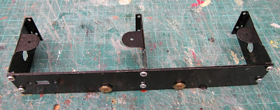
The bushes needed to be repositioned in the other sideframe as they were slightly skewed. With a little persuasion they were removed and re-inserted.

The wheels were threaded on to the axles, ..........

....... the motor positioned between the frames and the second sideframe was then screwed into place.


At this point, I decided to test the chassis, and so the battery pack was connected temporarily to the motor and the chassis given a a few laps of the main circuit on the railway.

The chassis ran fairly smoothly though I needed to adjust the back to back measurements a couple of times when the wheels dropped between the tracks. Buoyed by this success, I then decided to add the fly-cranks, which I felt could be quite tricky. The grub-screws were inserted into the brass fittings .......

...... and then the brass bearings were inserted into the coupling rods.

Inevitably, they were a tight fit and I found that by bevelling the top of the hole in the rods, with some very light filing of its upper edge, helped give the bearing a start on the axle.
To keep the bearings square during insertion, they were then squeezed in a vice.


The fly-cranks were then attached to the ends of the axles and the coupling rods attached using the circlips which were provided.

Quartering the fly-cranks on the other side was initially done by eye and then tweaked by running the chassis on the track until it ran more smoothly. The grub screws were then tightened and the chassis given a few more test-runs (and further fine-tuning).
The chassis was now set aside and my attention was turned to the construction of the body. My first job was to add the detailing to the bonnet. I started by gluing mesh to the radiator. To ensure the mesh was cut to the right size and shape, a card template was marked (by rubbing over the aperture with a grubby finger) and cut out.


Two pieces of mesh were then cut from the sheet provided .........

......... and glued in place with epoxy.

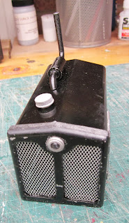
Next, the various appendages were added to the bonnet, starting with the exhaust pipe and silencer unit which was bolted underneath after a 3mm hole had been drilled in the bonnet.


Then the other trimmings were added, mostly glued into place with epoxy. Apart from a photo of a completed loco, there were no specific instructions as to where the items should be fixed into place. On the right side went an access door and a vent - while some sort of air intake was fixed atop.

On the other side went a louvred vent and another access door ..........

....... and the bezel was fitted around the headlight.
The LED which is provided for the headlight was soldered to its resistor and heatshrink insulation applied over the leads.

Two in-line sockets were then soldered on to the leads and the LED epoxied into place at the rear of the radiator.

Round-headed screws and nuts are provided to fix the cab rood to the sides, but I felt these looked somewhat overscale and unprototypical. Ideally, I would have used countersunk screws but I was concerned that the thinness of the metal, together with the size of the holes would have led to a flimsy joint. I therefore decided to use pop-rivets.

Detailing was added to the front of the cab ........

..... and the access hatch was fixed to the roof using the double-sided sticky pad provided.

and the spectacle plates were fitted .......

..... as were the handrails.

The footplate was tackled next. Captive nuts were epoxied in place to hold the screws which will hold the bonnet in place.

And then the footplate was bolted to the chassis, and the cab and bonnet temporarily fitted in place.
At this point, the wiring was soldered together. I had decided I would not use the manual speed controller which is provided with the kit as I wanted the loco to be radio controlled. I had already acquired a Mac5 controller from Brian Jones and so using the two DPDT switches which were provided with the kit, I wired up the motor, battery holders, controller, receiver and charging socket.

The components were then fixed temporarily in place for some field testing.

It soon became apparent that 9 volts was going to be insufficient to power the loco when pulling a load and so another battery holder was wired into the circuit to provide 12 volts.

As can be seen from this short video, 12 volts seemed adequate to power the loco with a train of tippler wagons up the 1:40 gradient on my railway. The weight of the metal body appeared to be sufficient for traction though as the test was with alkaline batteries there would be more weight when the bonnet was added and another couple of NiMH batteries were wired into the circuit.
Within a few days of creating this posting, the gears on the new gearbox stripped while test running the loco. My first thought was to see if I could find a suitable set of gears, the same size, preferably in metal, which would act as a direct replacement. I sent off for a 20:1 worm wheel and gear from Cambrian Models but found the dimensions are not comparable. I then decided to make my own gear housing for these gears from a U-shaped piece of 1.5mm thick brass shim.

This was folded up and the axle inserted together with the worm wheel and some nuts and washers to act as spacers. The assembly was then screwed on to the end of the motor ....


The gearbox assembly was soon installed into the chassis, with washers and brass tubing acting as spacers above the gearbox to ensure it was at the appropriate height.

The Deltang Tx22 system enables up to twelve locos to be controlled from one transmitter using the 2.4gHz waveband. This means it is quite reliable and also, because the combined receiver/controllers were originally developed for use in 00 scale locos, they are quite small. It also means they have an upper limit on the current load they can handle and while the system worked well with my other battery locos (eg see How I constructed an 0-6-2T based on the Southwold Railway loco No.4), it sometimes struggled to cope with the demands of the slightly stiff gearbox on this loco. However, following some discussion with the developer of the Deltang system, he adapted one of his receivers (the Rx102) to work with the Tx22 transmitter which enabled me to use the Brian Jones Mac Five controller, which can handle higher current loads. This receiver has now been further improved and is available on the Deltang website for others to use in their models.

Update 24/3/15 - Deltang have now developed a combined receiver/controller which can handle higher loads (up to 3 amps) - the Rx65b.
To increase the capacity inside the loco for holding the batteries and r/c gear, a simple control panel was constructed from off-cuts of plasticard and a few bits and pieces from the bits box.

This was then carefully positioned and superglued on to the footplate.


Next, attention was turned to mounting the LGB hook and loop couplings which I use on my railway. I would prefer to use something more realistic but as I am very keen on freight handling and shunting operations, I need something reliable and relatively easy to use. After determining the coupling-height, I removed the buffer beams from each end of the loco and made a couple of cuts for a slot sufficiently wide to accommodate a coupling and sufficiently deep to provide a bracket for mounting the coupling at the correct height when folded back.


After mounting the couplings with some self-tapping screws, the buffer beams were re-attached to the chassis (this time the correct way round) and given a coat of Plasticote signal red.

The two body parts were then given a coat of Halfords grey primer followed by two coats of Humbrol Brunswick Green from one of their rattle cans.

The loco was then reassembled for more test-running (you may have realised I am a little impatient at times! - as you can see, the masking tape is still attached to the radiator grille).

The control panel was given a coat of brown acrylics, with details picked out in white and brass-colour. The motion was painted red to match the buffer-beams.

The inside of the cab was painted cream and the handrails and spectacle plates picked-out in Plasticote brass paint.

The cab roof was painted with black acrylics......

..... and then came the interesting part - weathering. At first, I did some light weathering suggesting there were nooks and crannies which might have missed the cleaner's oily rag.

But I then decided to add a few rust spots.


Eventually, the whole loco was 'rusted' and a wash of mucky brown-black daubed over to dull down the paint and brasswork. A whitemetal porter figure was pressed into service as a driver.

As indicated earlier, nuts are epoxied on to the chassis to attach the body. With my various dis- and re-assembling I kept finding these easily became detached. I therefore tried some epoxy putty to fix the nuts inside the bonnet and the bolts inside the cab. So far they seem more secure but eventually I may try soldering them all in place. Epoxy resin doesn't seem to be as strong as it was when I were a lad!


Not having bolts of a suitable length I cut them shorted using a technique taught to me by my dad many many years ago (see How I shorten bolts). The nuts holding the cab in place were then slipped over the bolts ....

.... and tightened-up.

Up until now, I had avoided adding the sandboxes for the rear wheels as I was uncertain as to where I would be fitting the charge socket. I realised, of course, that the best position for the sand boxes was precisely where I'd put the charge socket, but decided with a small modification it could act as a moveable cover. A wedge was removed from the top with a saw and a file......


...... and it was then attached just below the socket ......

.... but left sufficiently loose to allow it to swivel aside.

After priming, it was then painted black as were the footboards which were attached beside it.
After a little more cosmetic touches here and there to add to the general air of utilitarian neglect, she was at last ready to enter service.

There are still a few more touches I now feel I would like to add.

For example, I'd like to install a fan and a representation of the radiator behind the grille....

...... and of course she will need to have a name, nameplates and a number to properly enter service.

And at the moment, the chassis and running gear looks a little too pristine.

But overall. although the build turned out to be more problematic than I had envisaged, she's now ready to assume her duties at the copper mine.

The driver has now been moved so he is half hanging out of the cab. He looked a bit unsteady where he was positioned before but now looks more workmanlike.

I will no doubt add more details as time moves on but I have now thought of a name for her.

Instead of "Jessie", the name under which she was marketed, she will become "Wynford", named after the Baron Tollemache's first wife (he was the benefactor of the railway! - see A short history of the railway). Nameplates have been ordered and there will be an official naming ceremony.

Update: How I added a sound card to the diesel
Update: Improving the mechanism for the diesel loco

However, not wishing to burn my boats and put all my eggs in one basket, I have decided to make the transition gently from one form of power to the other. My locos have to work hard pulling their trains up the 1:40 gradients and, until I am certain that battery powered locos will be equally up to the job, I want to experiment with battery power while retaining DCC track-power as the principal method of control.
Update (March 2015) I have now abandoned track power and control in favour of battery powered radio control (see Getting started with battery power). I now have ten locos which are battery powered with two awaiting conversion from track to battery power (see How I converted a loco from track to battery power). My anxieties about the pulling power of battery locos were unfounded. In fact, removing the friction of skates and pick-ups and increasing friction between wheels and rails as they no longer need to be polished, has resulted in a considerable improvement in pulling-power (see Manning Wardle load test - Barclay Load Test - Peckett Test run)
A fortunate purchase through a well known auction website resulted in a partially completed kit for a Jessie diesel locomotive from IP Engineering. The kit is no longer available but the kit arrived with two detailing packs and two motors and gearboxes.

Careful scrutiny of the gearbox revealed that the previous owner had experienced some difficulty in its construction - the worm wheel had been stripped and the worm itself was split.


By applying the glue with a cocktail stick I was able to keep the glue more or less under control and then left the assembly overnight to fully harden-off. Though it was with some anxiety that I connected the battery to the motor the following morning to find out whether or not I had been successful.Fortunately, all was well and so I was able to continue with the build.

I next turned my attention to the chassis, which had been partially constructed. The brass bushes had been epoxied into place and one of the side frames had been attached to the cross-members by self tapping screws.

The bushes needed to be repositioned in the other sideframe as they were slightly skewed. With a little persuasion they were removed and re-inserted.

The wheels were threaded on to the axles, ..........

....... the motor positioned between the frames and the second sideframe was then screwed into place.


At this point, I decided to test the chassis, and so the battery pack was connected temporarily to the motor and the chassis given a a few laps of the main circuit on the railway.

The chassis ran fairly smoothly though I needed to adjust the back to back measurements a couple of times when the wheels dropped between the tracks. Buoyed by this success, I then decided to add the fly-cranks, which I felt could be quite tricky. The grub-screws were inserted into the brass fittings .......

...... and then the brass bearings were inserted into the coupling rods.

Inevitably, they were a tight fit and I found that by bevelling the top of the hole in the rods, with some very light filing of its upper edge, helped give the bearing a start on the axle.
To keep the bearings square during insertion, they were then squeezed in a vice.


The fly-cranks were then attached to the ends of the axles and the coupling rods attached using the circlips which were provided.

Quartering the fly-cranks on the other side was initially done by eye and then tweaked by running the chassis on the track until it ran more smoothly. The grub screws were then tightened and the chassis given a few more test-runs (and further fine-tuning).
The chassis was now set aside and my attention was turned to the construction of the body. My first job was to add the detailing to the bonnet. I started by gluing mesh to the radiator. To ensure the mesh was cut to the right size and shape, a card template was marked (by rubbing over the aperture with a grubby finger) and cut out.


Two pieces of mesh were then cut from the sheet provided .........

......... and glued in place with epoxy.

Next, the various appendages were added to the bonnet, starting with the exhaust pipe and silencer unit which was bolted underneath after a 3mm hole had been drilled in the bonnet.


Then the other trimmings were added, mostly glued into place with epoxy. Apart from a photo of a completed loco, there were no specific instructions as to where the items should be fixed into place. On the right side went an access door and a vent - while some sort of air intake was fixed atop.

On the other side went a louvred vent and another access door ..........

....... and the bezel was fitted around the headlight.


Two in-line sockets were then soldered on to the leads and the LED epoxied into place at the rear of the radiator.

Round-headed screws and nuts are provided to fix the cab rood to the sides, but I felt these looked somewhat overscale and unprototypical. Ideally, I would have used countersunk screws but I was concerned that the thinness of the metal, together with the size of the holes would have led to a flimsy joint. I therefore decided to use pop-rivets.

Detailing was added to the front of the cab ........

..... and the access hatch was fixed to the roof using the double-sided sticky pad provided.

and the spectacle plates were fitted .......

..... as were the handrails.

The footplate was tackled next. Captive nuts were epoxied in place to hold the screws which will hold the bonnet in place.

And then the footplate was bolted to the chassis, and the cab and bonnet temporarily fitted in place.
At this point, the wiring was soldered together. I had decided I would not use the manual speed controller which is provided with the kit as I wanted the loco to be radio controlled. I had already acquired a Mac5 controller from Brian Jones and so using the two DPDT switches which were provided with the kit, I wired up the motor, battery holders, controller, receiver and charging socket.

The components were then fixed temporarily in place for some field testing.

It soon became apparent that 9 volts was going to be insufficient to power the loco when pulling a load and so another battery holder was wired into the circuit to provide 12 volts.

As can be seen from this short video, 12 volts seemed adequate to power the loco with a train of tippler wagons up the 1:40 gradient on my railway. The weight of the metal body appeared to be sufficient for traction though as the test was with alkaline batteries there would be more weight when the bonnet was added and another couple of NiMH batteries were wired into the circuit.
Within a few days of creating this posting, the gears on the new gearbox stripped while test running the loco. My first thought was to see if I could find a suitable set of gears, the same size, preferably in metal, which would act as a direct replacement. I sent off for a 20:1 worm wheel and gear from Cambrian Models but found the dimensions are not comparable. I then decided to make my own gear housing for these gears from a U-shaped piece of 1.5mm thick brass shim.

This was folded up and the axle inserted together with the worm wheel and some nuts and washers to act as spacers. The assembly was then screwed on to the end of the motor ....

.... together with a bracket for attaching the motor and gearbox to the chassis.

Unfortunately, my engineering skills were insufficient to ensure the worm and gear wheel meshed accurately. While the loco would happily travel in reverse, the gears lost their mesh when travelling forwards if even the slightest load was placed on it. After an appeal for suggestions on the G Scale Central forum, one of the community volunteered to make me another gearbox housing. I duly sent him the bits but he decided to use a 00 scale gear set which he had to hand.
His gearbox is considerably more robust than mine, though he was uncertain as to how long the 00 gears would last.


The gearbox assembly was soon installed into the chassis, with washers and brass tubing acting as spacers above the gearbox to ensure it was at the appropriate height.

Update 1/4/14 - This gearbox lasted about a year before the gears became worn and so a more radical solution to the problem was found. I replaced the entire mechanism with a USAt 0-4-0 motor block which slotted inside the IP chassis. This loco is now extremely reliable. (see How I improved my IP Jessie mechanism) . Here's a video of her with her new motor block.
Over this extended course of construction, I had discovered a new source of radio control equipment developed by an aero-modeller who was branching out into other areas of radio control.
The Deltang Tx22 system enables up to twelve locos to be controlled from one transmitter using the 2.4gHz waveband. This means it is quite reliable and also, because the combined receiver/controllers were originally developed for use in 00 scale locos, they are quite small. It also means they have an upper limit on the current load they can handle and while the system worked well with my other battery locos (eg see How I constructed an 0-6-2T based on the Southwold Railway loco No.4), it sometimes struggled to cope with the demands of the slightly stiff gearbox on this loco. However, following some discussion with the developer of the Deltang system, he adapted one of his receivers (the Rx102) to work with the Tx22 transmitter which enabled me to use the Brian Jones Mac Five controller, which can handle higher current loads. This receiver has now been further improved and is available on the Deltang website for others to use in their models.

Update 24/3/15 - Deltang have now developed a combined receiver/controller which can handle higher loads (up to 3 amps) - the Rx65b.
To increase the capacity inside the loco for holding the batteries and r/c gear, a simple control panel was constructed from off-cuts of plasticard and a few bits and pieces from the bits box.

This was then carefully positioned and superglued on to the footplate.


Next, attention was turned to mounting the LGB hook and loop couplings which I use on my railway. I would prefer to use something more realistic but as I am very keen on freight handling and shunting operations, I need something reliable and relatively easy to use. After determining the coupling-height, I removed the buffer beams from each end of the loco and made a couple of cuts for a slot sufficiently wide to accommodate a coupling and sufficiently deep to provide a bracket for mounting the coupling at the correct height when folded back.


After mounting the couplings with some self-tapping screws, the buffer beams were re-attached to the chassis (this time the correct way round) and given a coat of Plasticote signal red.

The two body parts were then given a coat of Halfords grey primer followed by two coats of Humbrol Brunswick Green from one of their rattle cans.

The loco was then reassembled for more test-running (you may have realised I am a little impatient at times! - as you can see, the masking tape is still attached to the radiator grille).

The control panel was given a coat of brown acrylics, with details picked out in white and brass-colour. The motion was painted red to match the buffer-beams.

The inside of the cab was painted cream and the handrails and spectacle plates picked-out in Plasticote brass paint.

The cab roof was painted with black acrylics......

..... and then came the interesting part - weathering. At first, I did some light weathering suggesting there were nooks and crannies which might have missed the cleaner's oily rag.

But I then decided to add a few rust spots.


Eventually, the whole loco was 'rusted' and a wash of mucky brown-black daubed over to dull down the paint and brasswork. A whitemetal porter figure was pressed into service as a driver.

As indicated earlier, nuts are epoxied on to the chassis to attach the body. With my various dis- and re-assembling I kept finding these easily became detached. I therefore tried some epoxy putty to fix the nuts inside the bonnet and the bolts inside the cab. So far they seem more secure but eventually I may try soldering them all in place. Epoxy resin doesn't seem to be as strong as it was when I were a lad!


Not having bolts of a suitable length I cut them shorted using a technique taught to me by my dad many many years ago (see How I shorten bolts). The nuts holding the cab in place were then slipped over the bolts ....

.... and tightened-up.

Up until now, I had avoided adding the sandboxes for the rear wheels as I was uncertain as to where I would be fitting the charge socket. I realised, of course, that the best position for the sand boxes was precisely where I'd put the charge socket, but decided with a small modification it could act as a moveable cover. A wedge was removed from the top with a saw and a file......


...... and it was then attached just below the socket ......

.... but left sufficiently loose to allow it to swivel aside.

After priming, it was then painted black as were the footboards which were attached beside it.
After a little more cosmetic touches here and there to add to the general air of utilitarian neglect, she was at last ready to enter service.

There are still a few more touches I now feel I would like to add.

For example, I'd like to install a fan and a representation of the radiator behind the grille....

...... and of course she will need to have a name, nameplates and a number to properly enter service.

And at the moment, the chassis and running gear looks a little too pristine.

But overall. although the build turned out to be more problematic than I had envisaged, she's now ready to assume her duties at the copper mine.
Update (22/8/13)
Her chassis is now weathered with weathering powders and a fan has been added behind the radiator grille. The fan is from a computer and runs off 12v but when connected it spins so fast you can't see it. The blades of the fan have been painted silver to make them more visible behind the grille.
The driver has now been moved so he is half hanging out of the cab. He looked a bit unsteady where he was positioned before but now looks more workmanlike.

I will no doubt add more details as time moves on but I have now thought of a name for her.

Instead of "Jessie", the name under which she was marketed, she will become "Wynford", named after the Baron Tollemache's first wife (he was the benefactor of the railway! - see A short history of the railway). Nameplates have been ordered and there will be an official naming ceremony.

Update: How I added a sound card to the diesel
Update: Improving the mechanism for the diesel loco
3 comments:
Excellent article/blog. Really help ful for the rest of us modellers looking to build or modify battery RC locos. Thanks
Thanks. A really useful article/blog. Lots of tips and construction ideas. Your pictures and explanations are excellent.
Thanks - I hope it helps. This particular kit is no longer available but it hopefully gives some idea of how IP Engineering kits go together. I've just added another update to the end of the article showing how I've since improved the loco's mechanism by using a USA Trains motor block. She's now one of my most reliable runners.
Post a Comment